Installation
Transport System Installation
260 MagneMotion
Rockwell Automation Publication MMI-UM002F-EN-P - October 2022
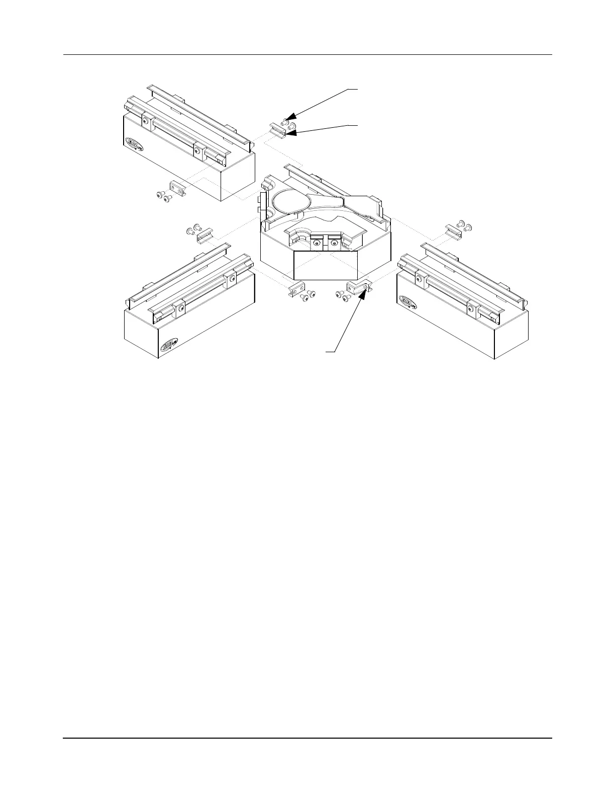
Figure 5-14: Install High Payload Switch
1. Loosen the M6 bolt used to secure the switch to the motor mount for all switches being
adjusted if necessary.
2. For aluminum rails, install the appropriate V-braces at all guide rail joints using M6 x
12 mm screws and tighten finger-tight to pull the rails together.
NOTE: The guide rail joints on the aluminum rails contain locking inserts, which
limit the depth of insertion when finger tightening.
For stainless steel rails, install the appropriate V-braces at all guide rail joints using
M6 x 12 mm screws with Loctite 243 and tighten finger-tight to pull the rails together.
3. Using fingers, align the rails at the switch joints as shown in Figure 5-13 and
Figure 5-14. Tighten the two M6 x 12 mm screws on each V-brace at that switch joint
to 3.4 N•m [30 in•lb] with a T30 Torx bit.
4. Tighten the M6 bolt to 5.5 N•m [49 in•lb] with a 10 mm Hex socket to secure the
switch to the motor mount.
For stainless steel rails the Loctite must cure for 2 hours at 22° C [72° F] before using
the transport system.
5. Repeat Step 3 at all switch joints.
6. Repeat Step 4 at all switches.
Standard V-brace
(5X 200-2002-XX)
LF Switch V-brace
(200-2450-XX)
M6 x 12 mm Screw
(2X per V-brace)
 Loading...


