Specifications and Site Requirements
Mechanical Specifications
MagneMover LITE User Manual 181
Rockwell Automation Publication MMI-UM002F-EN-P - October 2022
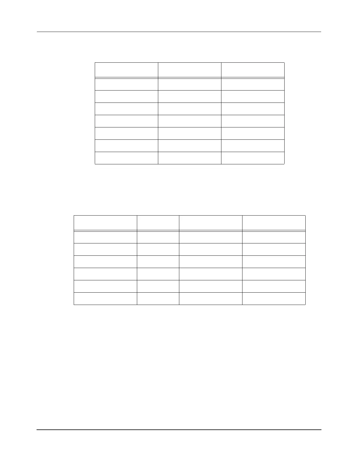
Table 4-4: Stand System Heights
Leg Height System Height Catalog #
*
* The “X” in the catalog number represents the stand width (see Table 4-5)
505 mm [19.9 in] 745 mm [29.3 in] 200-1991-X0
560 mm [22.0 in] 800 mm [31.5 in] 200-1991-X4
575 mm [22.6 in] 815 mm [32.1 in] 200-1991-X5
598 mm [23.5 in] 838 mm [33.0 in] 200-1991-X3
639 mm [25.2 in] 879 mm [34.6 in] 200-1991-X1
649 mm [25.6 in] 889 mm [35.0 in] 200-1991-X6
732 mm [28.8 in] 972 mm [38.3 in] 200-1991-X2
Table 4-5: Stand System Widths
Parallel Motors
*
* Maximum number of motors supported, minimum motor spacing is 250 mm center-to-center.
Legs Stand Widths Catalog #
†
† The “X” in the catalog number represents the stand height (see Table 4-4)
1 1 50 mm [2.0 in] 200-1991-0X
2 2 300 mm [11.8 in] 200-1991-1X
3 2 550 mm [21.7 in] 200-1991-2X
4 2 800 mm [31.5 in] 200-1991-3X
5 3 1050 mm [41.3 in] 200-1991-4X
6 3 1300 mm [51.2 in] 200-1991-5X
 Loading...


