Installation
Option Installation
MagneMover LITE User Manual 291
Rockwell Automation Publication MMI-UM002F-EN-P - October 2022
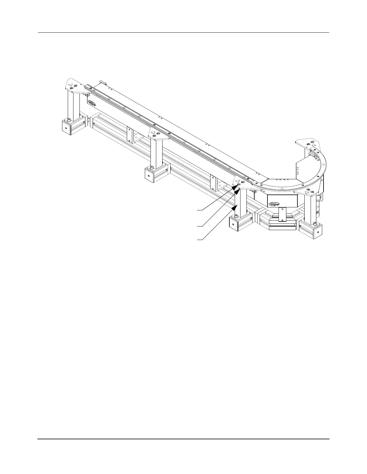
Secure Spine Plates to Support Posts
Once all rails have been properly aligned and secured to the spine plates, the spine plates must
be firmly secured to the top of each support post as shown in Figure 5-40.
Figure 5-40: Securing Precision Rail Spine Plates to Support Posts
1. Starting with the M6 x 10 mm low head socket cap screw closest to the rail, tighten it
to 3.2 N•m [28 in•lb] with a 5 mm Hex wrench.
2. Check the rail to make sure it is still properly aligned.
3. Tighten the second M6 screw on the spine plate to 3.2 N•m [28 in•lb] with a 5 mm
Hex wrench.
4. Select to the next closest spine plate and repeat Step 1 through Step 3. Continue secur-
ing each spine plate to its support post until all spine plates are secure.
Install the Precision Rail Vehicles
Install vehicles on closed loop systems before closing the loop to eliminate the need to remove
a precision rail or change the factory settings on the vehicles (see Installing Vehicles with
Rails Removed on page 430. If all rail segments have been installed, see Installing Vehicles
Without Removing Rails on page 431.
Spine Plate
Support Post
M6 Low Head SCS
(2X)
 Loading...


