Installation
Option Installation
284 MagneMotion
Rockwell Automation Publication MMI-UM002F-EN-P - October 2022
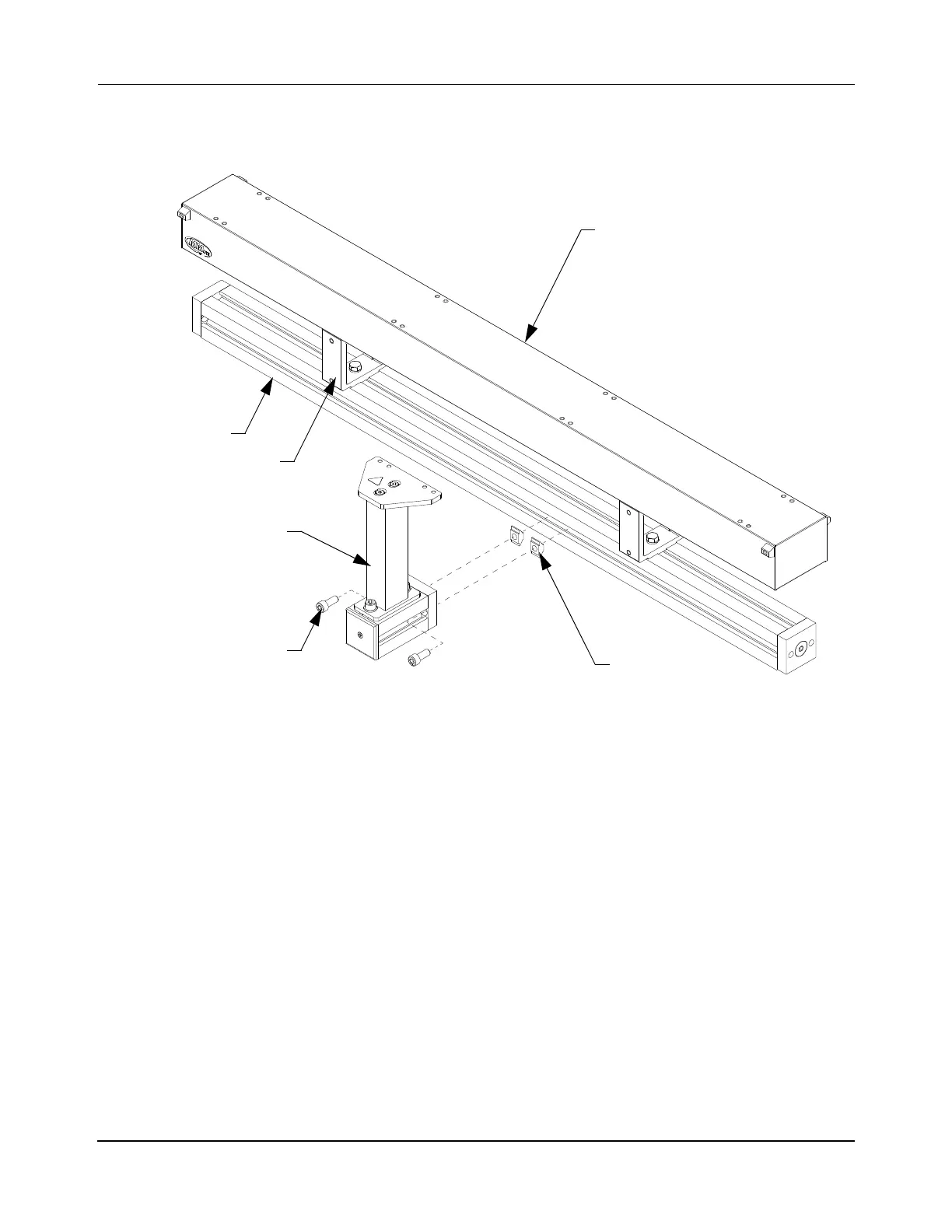
Attach Precision Rail Support Posts to the Beam
Once all support posts are assembled, install them onto the beam as shown in Figure 5-31.
Figure 5-31: Attach Precision Rail Support Post Assemblies to Beam
1. Locate each support post assembly at the appropriate position on the transport system.
2. Remove the M8 T-nuts from the connecting plate and install them into the channel on
the outside of the beam at the location for the support post and rotate into position.
3. Loosely secure each support post assembly to the T-nuts with the M8 SHC screws.
Finger-tighten then back off one-half turn to provide the parts a small amount of
movement relative to each other to allow adjustment.
NOTE: Make sure that the rail mounting edge of the spine plate is oriented towards
the motor.
M8 T-Nut
M8 x 20 Screw
Motor
Motor Mount
Beam
Support Post
Assembly
(2X)
(2X)
 Loading...


