Specifications and Site Requirements
Electrical Specifications
208 MagneMotion
Rockwell Automation Publication MMI-UM002F-EN-P - October 2022
Straight and Curve Motors
See 1000 Millimeter Motors through 125 Millimeter Radius 90° Curve Motors for mechanical
drawings.
NOTE: The motors draw an additional 15 W of power per vehicle (puck) when the vehicle is
moving at maximum acceleration or velocity (see Table 4-9).
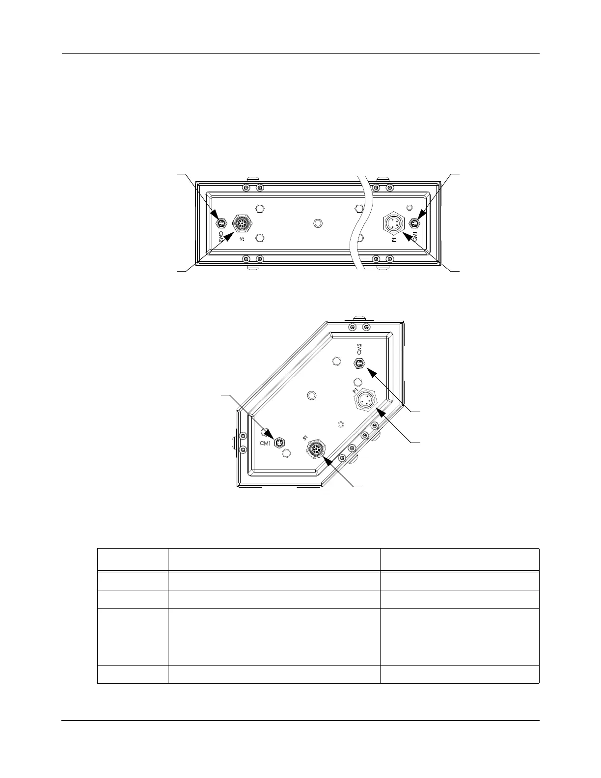
Figure 4-56: MagneMover LITE RS-422 Motor Electrical Connections
Table 4-10: MagneMover LITE RS-422 Motor Electrical Connections
Label Description Connector Type
CM1 RS-422 communication M8 Nano-Mizer
®
, 4-Pin, Plug
CM2 RS-422 communication M8 Nano-Mizer, 4-Pin, Plug
P1 Power +36V DC ±10%
1000 mm motor – 1.5 A typical 5.0 A max
250 mm motor – 0.4 A typical, 1.2 A
max
Curve motor – 0.4 A typical, 1.2 A max
Mini-Conn-X
®
, 4-Pin, Plug
S1
*
* The Sync Option Connector is only present if the Synchronization option is installed. If the Sync Option con-
nector is not installed, a low-profile cap is installed to cover the connector mounting hole.
External Synchronization Micro-Mizer
®
, 8-Pin, Plug
Power
RS-422
Sync Option
Power
Sync Option
Straight Motor Sections
Curve Motor Sections
Bottom View
Bottom View
RS-422
Connector
Connector
Connector
Connector
Connector
RS-422
Connector
Connector
RS-422
Connector
 Loading...


