Operation
Theory of Operation
320 MagneMotion
Rockwell Automation Publication MMI-UM002F-EN-P - October 2022
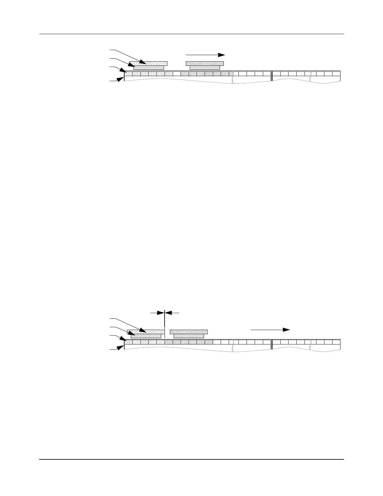
Figure 6-3: Representation of Moving Vehicles Per Motor Block
• The vehicle master uses the position of the most recently acquired block farthest from
the vehicle as an interim destination (target) to calculate the next profile setpoint (P
set
,
V
set
, and A
set
).
• A new interim destination (target) block is only granted if the block has not been allo-
cated to another vehicle (permission is granted for only one vehicle per motor block).
• A new target is requested only immediately before the vehicle must start slowing
down for its current target to minimize the number of committed blocks and to make
sure brick-wall headway is maintained.
• Permission to enter a motor block is only granted after the previous vehicle has exited
the block and released ownership.
• Each vehicle is controlled in such a manner that it is always able to stop in the last
motor block it was granted permission to enter.
Block Ownership
The minimum distance two vehicles can be from each other is 3 mm [0.12 in], since the end of
each vehicle maintains a space of 1.5 mm [0.0.6 in] from the end of the owned motor block in
the direction of motion for anti-collision. This minimum distance is based on the length of the
vehicle, not the magnet array. Figure 6-4 shows that when any portion of a vehicle is over a
motor block, the vehicle owns that whole block. The vehicle positions in Figure 6-4 show that
the vehicles could be closer together, but vehicle separation is based on the length of the con-
figured payload or vehicle and block ownership, not the length of the magnet array.
Figure 6-4: Representation of Block Ownership by Vehicle
When vehicles are placed in queue, they get as close to their commanded position as possible
without violating the block boundaries as shown in Figure 6-4. When trying to create stations
that put vehicle next to each other, the vehicle positions and the space that a vehicle occupies
in a motor block must be considered, as shown in Figure 6-4.
Block Release
The controller for each motor releases ownership of blocks when the vehicle exits the block
and is at least 1.5 mm away from that block. Block ownership is also released if the vehicle is
deleted.
Vehicle
Motor
Block
Magnet Array
Downstream Motion
Vehicle
Motor
Block
Magnet Array
Downstream Motion
1.5 mm
 Loading...


