Design Guidelines
Transport System Design
MagneMover LITE User Manual 115
Rockwell Automation Publication MMI-UM002F-EN-P - October 2022
Guideways
As with any conveyance technology, vehicle motion imparts dynamic loads on the guideway
system. Make sure that the guideway is adequately secured to a rigid, permanent structure,
such as the equipment the guideway is associated with or the floor, wall, or ceiling, which can
reduce vibrations and other stresses on the system.
Custom Guideway Design
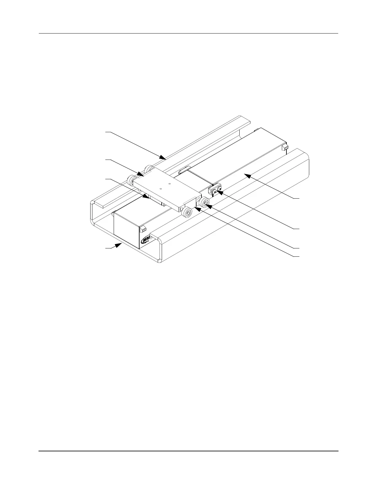
Figure 3-43: MagneMover LITE Railless Transport System, Single Vehicle
Basic guideway design guidelines and considerations:
• The guideway can have any orientation in relation to the motors and vehicles as long
as the magnet array on the vehicle is held in position next to the top of the motor.
• The guideway must hold the motors in position to make sure that the spacing from
motor to motor is maintained at 1 mm and does not change (see Figure 3-7).
• The guideway must hold the motors and support the vehicles to make sure that the
vehicle gap (see Figure 3-25) is maintained throughout the system.
• The guideway must provide sufficient space around the motor mounting surface for all
connectors and for the bend radius of all cables.
• Keep the guide rails on which the vehicles move flat to within ±0.5 mm to minimize
the variation in the vehicle gap throughout the transport system. Maintaining a tight
tolerance allows the vehicle gap to be as small as possible, which maximizes vehicle
thrust.
• When using curved guideways, make sure that the guideway material supports curv-
ing.
• The payload, vehicle mass, and motor mass must be within the limits of the guideway.
Motor
Wheel
Guideway
Motor Mount
Magnet Array
Vehicle
Guide Plate
V-brace
 Loading...


