Installation
Transport System Installation
254 MagneMotion
Rockwell Automation Publication MMI-UM002F-EN-P - October 2022
Motor Installation
Each Ethernet motor has a label that identifies its MAC address. These labels are attached to
either the bottom or side of the motor. Record this MAC address before installing the motor to
simplify configuration tasks.
Installing Cable Chase Cover Brackets
If cable chase covers are used, install the brackets for attaching the covers to the standard
motor mounts before installing the mounts on the motors and switches.
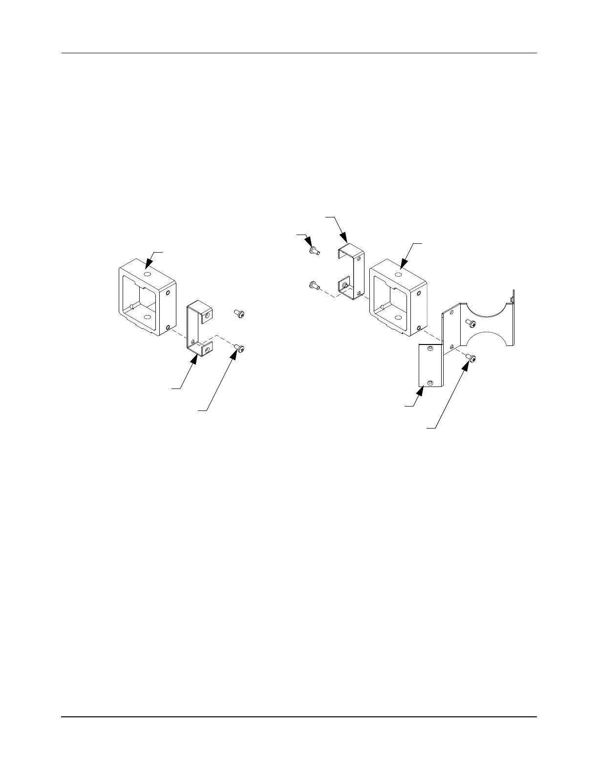
Figure 5-8: Installing Cable Chase Cover Mounting Brackets
1. Install a curve bracket on one side of the curve motor mount with two M5 x 8 mm
screws and tighten to 1.6 N•m [14 in•lb] with a Phillips bit.
2. Install a curve bracket on one side of the switch motor mount with two M5 screws and
tighten to 1.6 N•m [14 in•lb] with a Phillips bit.
3. Install a switch bracket to the other side of the switch motor mount with two M5
screws and tighten to 1.6 N•m [14 in•lb] with a Phillips bit.
Switch Bracket
M5 x 8 mm Screw
Curve Bracket
M5 x 8 mm Screw
Motor Mount
M5 x 8 mm Screw
(2X)
(2X)
(2X)
Curve Motor Mounts (typical) Switch Mounts (typical)
Motor Mount
 Loading...


