Teach-in | Turning cycles
5
HEIDENHAIN | MANUALplus 620 | User's Manual | 12/2017
217
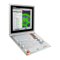
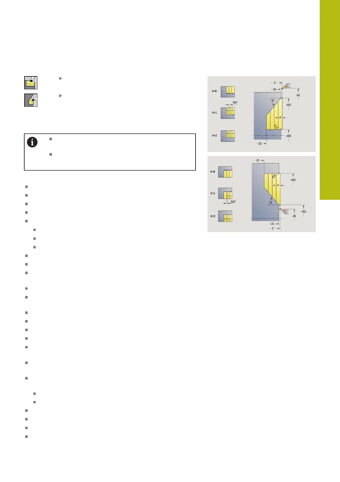
Cutting, transverse plunge
Select Roughing cycles lon/trans
Select Plunge transv.
The cycle roughs the area described by the Start point contour,
End point contour and Plunging angle.
The tool plunges with the maximum possible angle,
leaving material remaining
The steeper the tool plunges into the material, the
greater the feed rate decrease (max. 50 %)
Cycle parameters:
X, Z: Start point
X1, Z1: Start point contour
X2, Z2: End point contour
P: Feed depth – Maximum infeed depth
H: Contour smoothing
0: With each cut
1: With the last cut
2: No smoothing
A: Plunging angle (range: 0° <= A < 90°; default: 0°)
W: Final angle (range: 0° <= W < 90°; default: 0°)
G47: Safety clearance
Further information: "Safety clearance G47", Page 180
T: Tool number – turret pocket number
G14: Tool change point
Further information: "Tool change point G14", Page 180
ID: ID no.
S: Cutting speed or Constant speed
F: Feed per revolution
MT: M after T: M function that is executed after the tool call T
MFS: M at beginning: M function that is executed at the
beginning of the machining step
MFE: M at end: M function that is executed at the end of the
machining step
WP: No. of spindle – Displays which workpiece spindle is used
to execute the cycle (machine-dependent)
Main drive
Opposing spindle for rear-face machining
BW: Angle in the B axis (machine-dependent)
CW: Reverse the tool (machine-dependent)
HC: Shoe brake (machine-dependent)
DF: Miscellaneous function (machine-dependent)

 Loading...