ICP programming | Contour elements – turning contour
6
HEIDENHAIN | MANUALplus 620 | User's Manual | 12/2017
453
Turning contour form elements
Chamfer or rounding
Programming a chamfer or rounding radius:
Select the form elements
Select a chamfer
Enter the Cham. width BR
Alternative: Select a rounding radius
Enter the Rounding radius BR
Enter the chamfer or rounding as first contour
element: Element pos AN
Parameters:
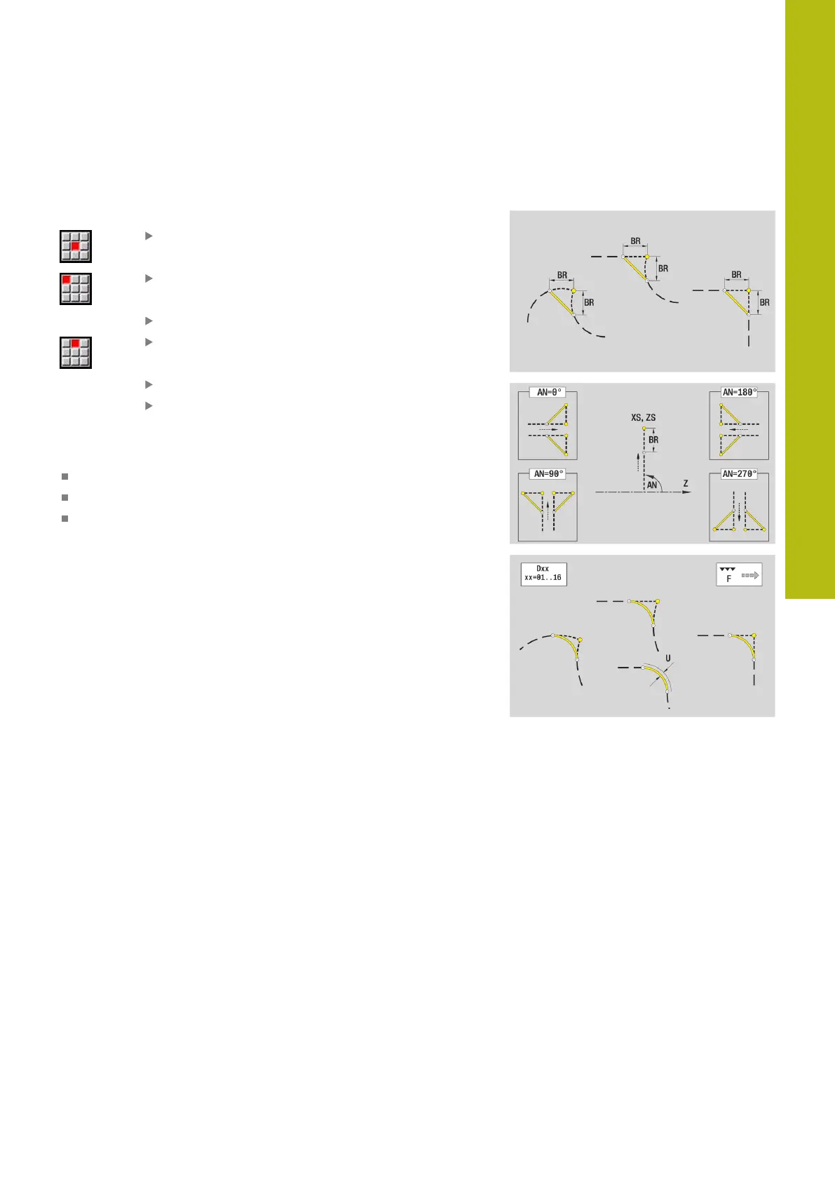
BR: Cham. width or Rounding radius
AN: Element pos
U, F, D, FP:
Further information: "Machining attributes", Page 418
Chamfers or rounding radii are defined at contour corners.
A contour corner is the point of intersection between the
approaching contour element and the departing contour element.
A chamfer or rounding cannot be calculated until the departing
contour element is known.
ICP integrates the chamfer or rounding in the G1, G2 or G3 basic
element in smart.Turn mode of operation.
Contour begins with a chamfer or a rounding radius: Enter
the position of the intended corner as starting point. Then, in the
form element menu, select chamfer or rounding radius. Since
the approaching contour element is missing, you enter the
element position AN to clearly define the position of the chamfer
or rounding radius.
Example of an outside chamfer at start of contour: If you
program Element pos AN=90°, the intended approaching reference
element is a transverse element in the positive + X direction.
ICP converts a chamfer or rounding at the start of the contour to a
linear or circular element.

 Loading...