Teach-in | Milling cycles
5
HEIDENHAIN | MANUALplus 620 | User's Manual | 12/2017
363
Axial slot
Select Milling
Select Axial slot
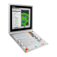
This cycle mills a slot on the face of the workpiece. The slot width
equals the diameter of the milling cutter.
Cycle parameters:
X, Z: Start point
C: Spindle angle – C-axis position
X1: Slot target point in X (diameter value)
C1: Angle of slot target pt. (default: spindle angle C)
L: Slot length
A1: Angle to X axis (default: 0°)
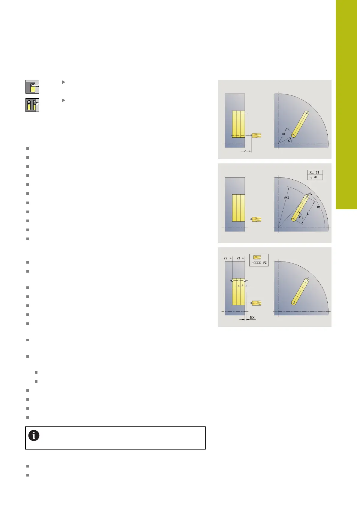
Z1: Millg. top edge (default: Starting point Z)
Z2: Milling floor
P: Feed depth (default: total depth of one infeed)
FZ: Approach feed (default: active feed rate)
SCK: Safety clearance
Further information: "Safety clearances SCI and SCK",
Page 180
T: Tool number – turret pocket number
G14: Tool change point
Further information: "Tool change point G14", Page 180
ID: ID no.
S: Cutting speed or Constant speed
F: Feed per revolution
MT: M after T: M function that is executed after the tool call T
MFS: M at beginning: M function that is executed at the
beginning of the machining step
MFE: M at end: M function that is executed at the end of the
machining step
WP: No. of spindle – Displays which workpiece spindle is used
to execute the cycle (machine-dependent)
Main drive
Opposing spindle for rear-face machining
BW: Angle in the B axis (machine-dependent)
CW: Reverse the tool (machine-dependent)
HC: Shoe brake (machine-dependent)
DF: Miscellaneous function (machine-dependent)
Type of machining for technology database access:
Milling
Parameter combinations for the position and orientation of the slot:
X1, C1
L, A1

 Loading...