Introduction and fundamentals | Fundamentals
1
HEIDENHAIN | MANUALplus 620 | User's Manual | 12/2017
53
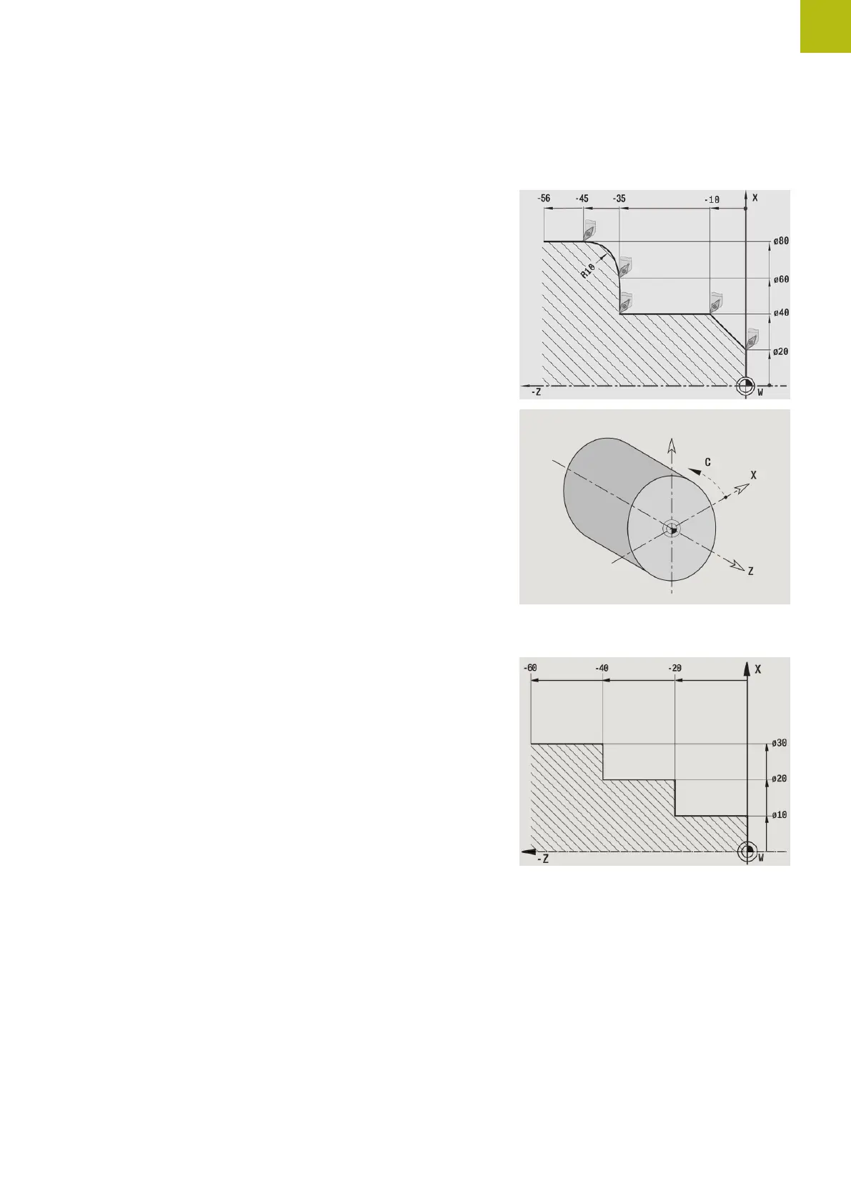
Coordinate system
The meanings of the coordinates X, Y, Z, and C are specified in DIN
66 217.
The coordinates entered for the principal axes X, Y and Z are
referenced to the workpiece datum. The angles entered for the
rotary axis (C axis) are referenced to the datum of the C axis.
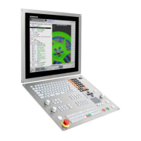
The axis designations X and Z describe positions in a two-
dimensional coordinate system. As you can see from the figure to
the center right, the position of the tool tip is clearly defined by its
X and Z coordinates.
The control can connect points by linear and circular paths of
traverse (interpolations). Workpiece machining is programmed by
entering the coordinates for a succession of points and connecting
the points by linear or circular paths of traverse.
Like the paths of traverse, you can also describe the complete
contour of a workpiece by defining single points through their
coordinates and connecting them by linear or circular paths of
traverse.
Positions can be programmed to an accuracy of 1 µm (0.001 mm).
This is also the accuracy with which they are displayed.
Absolute coordinates
If the coordinates of a position are referenced to the workpiece
datum, they are referred to as absolute coordinates. Each position
on a workpiece is clearly defined by its absolute coordinates.

 Loading...