ICP programming | Front face contours in smart.Turn mode of operation
6
484
HEIDENHAIN | MANUALplus 620 | User's Manual | 12/2017
Circular pattern on front face
Reference data of face:
ID: Contour
PT: Milling depth
ZR: Reference dimension
Parameters of figure:
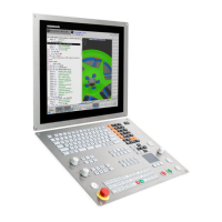
XK, YK: Center of pattern (in Cartesian coordinates)
QP: Quantity of points in pattern
DR: Dir.rot. (default: 0)
DR = 0, without EP: Figures are arranged on a full circle
DR = 0, with EP: Figures are arranged on the longer circular
arc
DR = 0, with EPi: The algebraic sign of EPi defines the
direction (EPi < 0: clockwise)
DR = 1, with EP: clockwise
DR = 1, with EPi: clockwise (algebraic sign of EPi has no
effect)
DR = 2, with EP: counterclockwise
DR = 2, with EPi: counterclockwise (algebraic sign of EPi has
no effect)
DP: Diameter
AP: Start angle (default: 0°)
EP: Final angle (no entry: the pattern elements are distributed
evenly around 360°)
EPi: Final angle – Angle between two figures
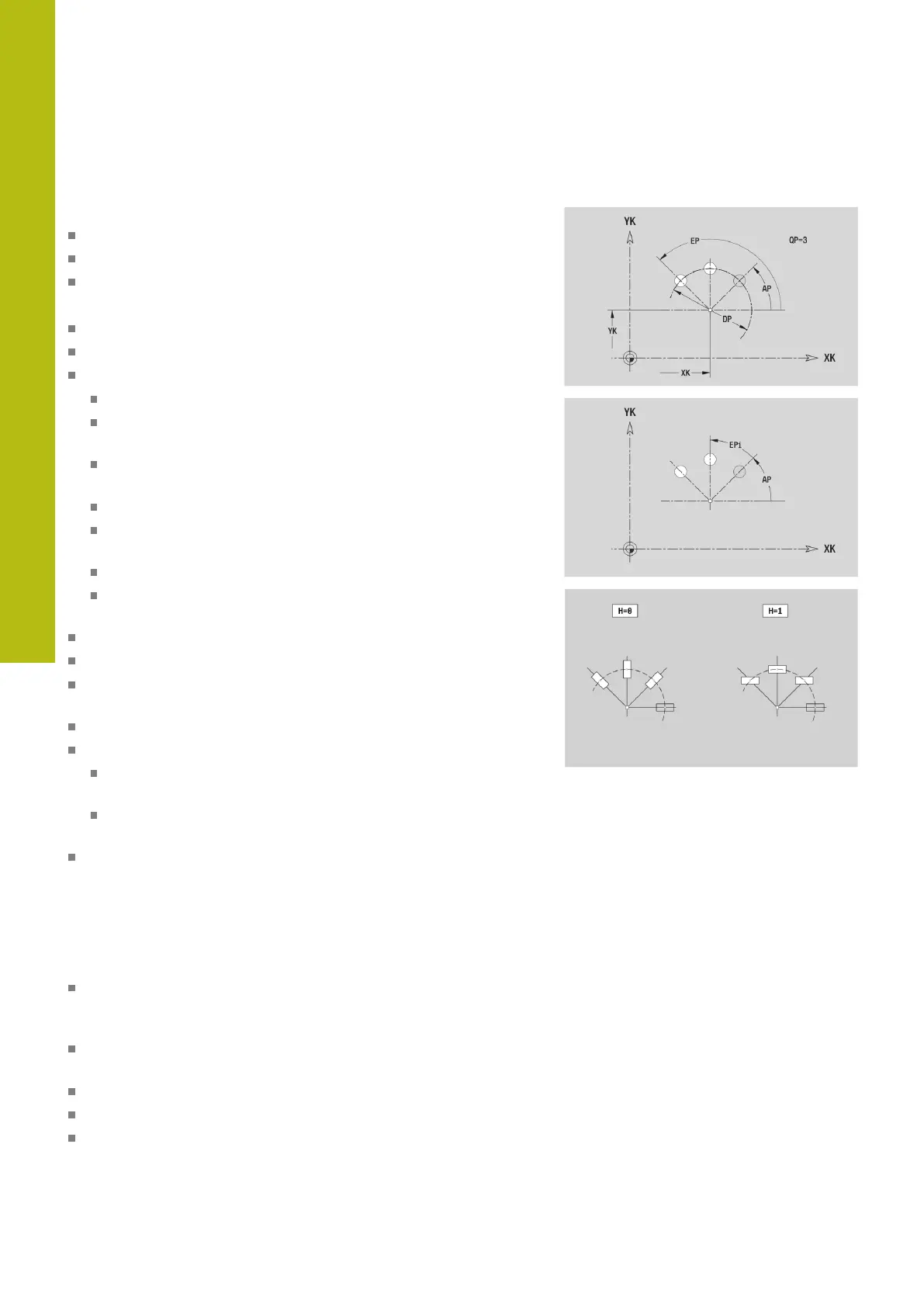
H: Element pos
0: Normal – The figures are rotated around the circle center
(rotation)
1: Master – The position of the figure relative to the
coordinate system remains unchanged (translation)
Parameters of the selected figure/hole
You can use the Select reference plane function to determine the
Reference dimension ZR.
Further information: "Reference data and nested contours",
Page 472
ICP generates the following:
The FRONT section code with the Reference dimension
parameter. In nested contours, ICP generates only one section
code
a G308 with the Contour name and Milling depth or Boring
depth (–1*BT) parameters
A G402 with the parameters of the pattern
The G code and the parameters of the figure/hole
A G309

 Loading...