ICP programming | C-axis and Y-axis machining in smart.Turn mode of operation
6
472
HEIDENHAIN | MANUALplus 620 | User's Manual | 12/2017
Reference data and nested contours
When describing a milling contour or hole, you define the
reference plane. The reference plane is the position on which the
milling contour or the hole is created.
Frontface (C axis): The Z position (Reference dimension)
Surface (C axis): The X position (Reference diameter)
Frontface (Y axis): The Z position (Reference dimension)
Surface (Y axis): The X position (Reference diameter)
It is also possible to nest milling contours and holes. Example:
Defining a slot in a rectangular pocket. Holes are drilled inside this
slot. You use the reference plane to specify the positions of these
elements.
ICP supports the selection of the reference plane. The following
reference data are loaded during selection of a reference plane.
Frontface: Reference dimension
Surface: Reference diameter
Frontface: Reference dimension, spindle angle, limit diameter
Surface: Reference diameter, spindle angle
Selecting a reference plane:
Select contour, figure, hole, pattern, single surface or polygon
Press the Select reference plane soft key
ICP displays the finished part and, if available, the
contours already defined
Use the soft keys (see table) to select the
reference dimension, reference diameter or
existing milling contour as reference plane
Confirm the reference plane
ICP loads the values of the reference plane as
reference data
Complete the reference data and describe the
contour, figure, hole, pattern, single surface or
polygon
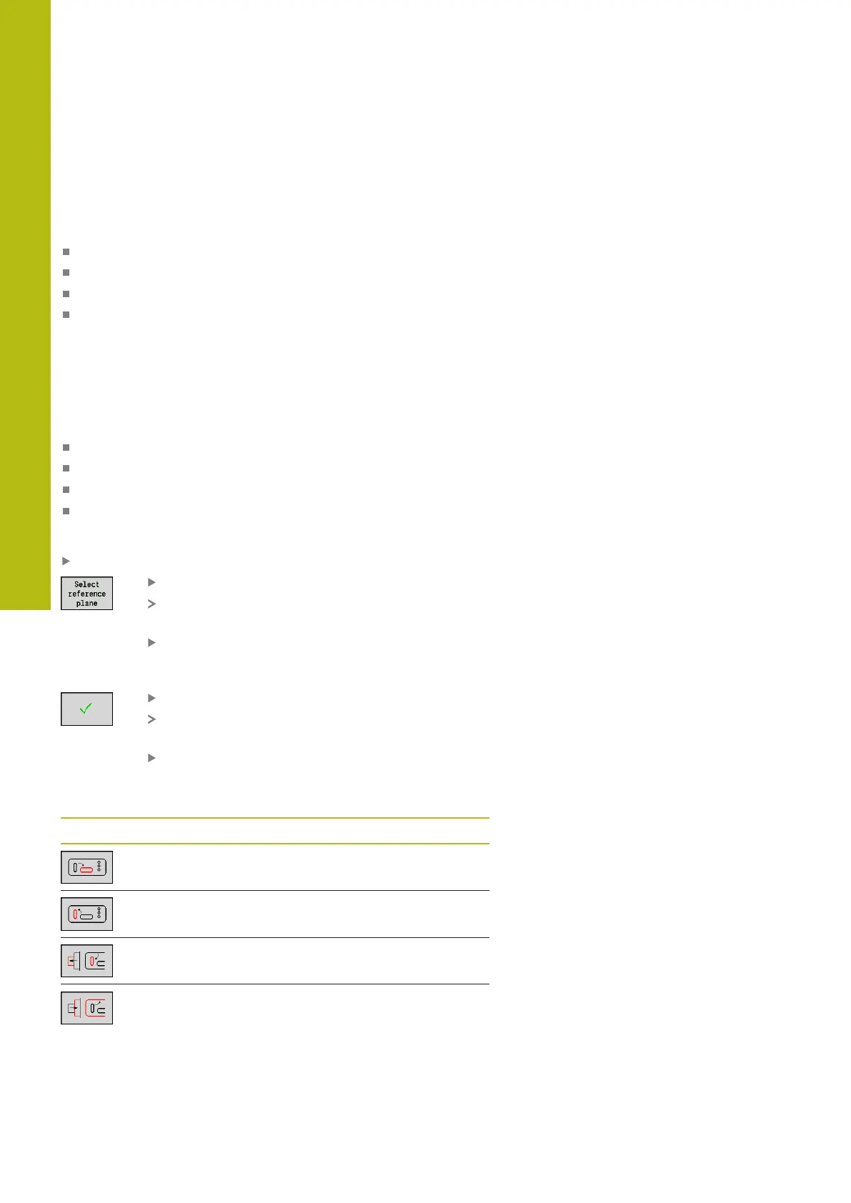
Soft keys for nested contours
Switch to the next contour of the same
reference plane
Switch to the previous contour of the same
reference plane
Switch to the next nested contour
Switch to the previous nested contour

 Loading...