ICP programming | Loading existing contours
6
HEIDENHAIN | MANUALplus 620 | User's Manual | 12/2017
527
DXF contours (option)
Contours that exist in DXF format are imported with the ICP editor.
You can use DXF contours both for the Teach-in submode and for
the smart.Turn mode of operation.
Requirements of a DXF contour:
Only two-dimensional elements
The contour must be in a separate layer (without dimension
lines, without wraparound edges, etc.)
Depending on the setup of the lathe, contours for turning
operations must be either in front of or behind the workpiece
No full circles, no splines, no DXF blocks (macros), etc.
The control supports all DXF formats.
Contour preparation during the DXF import: Since the DXF
format is fundamentally different from the ICP format, the contour
is converted from DXF to ICP format during the import.
The process makes the following changes:
Polylines are transformed into linear elements
Gaps between contour elements that are < 0.01 mm are closed
Open contours are described from right to left (starting point:
right)
The starting point on closed contours is specified according to
internal rules
The rotational direction for closed contours is counterclockwise
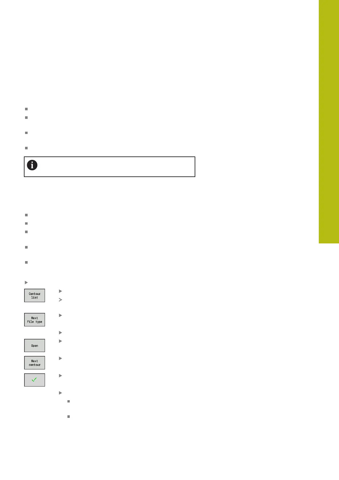
Integrating a DXF contour:
Activate the ICP editor submode
Press the Contour list soft key
The ICP editor submode opens the Select ICP
contours window
Press the Next file type soft key until the DXF
contours are displayed (extension: .dxf)
Select the file
Open the selected file
Select the DXF layer
Load the selected contour
Complete the contour, if necessary
Workpiece blank or finished part contour:
Complete or adapt the contour
C axis contour: Complete the reference data

 Loading...