ICP programming | Contours in the YZ plane
6
510
HEIDENHAIN | MANUALplus 620 | User's Manual | 12/2017
6.15 Contours in the YZ plane
In smart.Turn mode of operation, ICP provides the following
contours for machining with the Y axis:
Complex contours defined with individual contour elements
Figures
Holes
Pattern of figures or holes
Single surface
Polygon
Enter the dimensions of the YZ plane contour elements in
Cartesian or polar coordinates. You can switch between them by
soft key. You can mix Cartesian coordinates and polar coordinates
to define a point.
Soft keys for polar coordinates
Switch the field to entering the angle W
Switch the field to entering the radius P
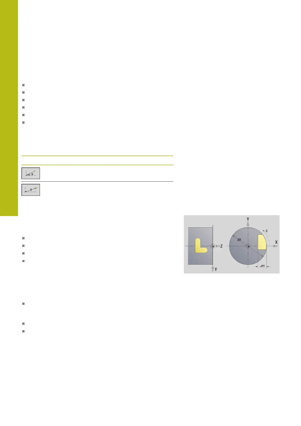
Reference data in YZ plane
The reference data is followed by the contour definition with
individual contour elements.
Reference data of milling operations:
ID: Contour
PT: Milling depth
C: Spindle angle
XR: Reference diameter
You can use the Select reference plane function to determine the
Reference diameter XR.
Further information: "Reference data and nested contours",
Page 472
ICP generates the following:
The SURFACE Y section code with the Reference diameter
and Spindle angle parameters. The section code is omitted for
nested contours.
A G308 with the Contour name and Milling depth parameters
A G309 at the end of the contour description

 Loading...