Graphic simulation | Views
7
HEIDENHAIN | MANUALplus 620 | User's Manual | 12/2017
539
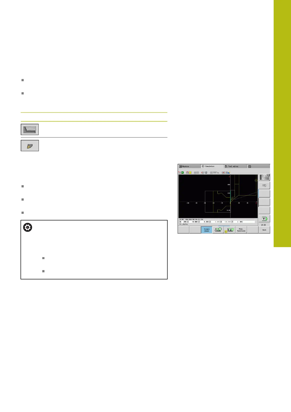
Tool display
You select by soft key whether the tool cutting edge or the light
dot is shown:
The tool cutting edge is shown with the correct angles and
cutting radius, as defined in the tool database
Light dot: A white square (light dot) is shown at the currently
programmed position. The light dot represents the position of
the imaginary cutting edge
Miscellaneous functions soft keys
Switch between wire-frame graphics and
cutting-path graphics
Switch between light-dot and cutting-edge
view
Depicting the tool holder in Simulation submode
The control can depict the associated tool holder with the
corresponding dimensions in addition to the tool's cutting edge.
The requirements for this are:
Creating a new tool holder in the Holder editor or selecting an
existing holder
Describing the tool holder with the required parameters (type,
dimensions and position)
The appropriate tool holder must be assigned to the tool (HID)
Refer to your machine manual.
The depiction of the tool carrier depends on the
machine.
The graphic displays a tool carrier if the following
requirements are fulfilled:
The machine tool builder has saved a description of
the tool carrier, e.g. B axis head
You have assigned a tool holder to a tool

 Loading...