MFP OPTIONS: B064 SERIES
SM 1-85 B064 Series/B140 Series/G126
Installation
Installation Procedure
CAUTION
Switch the machine off and unplug the machine before starting the
following procedure.
NOTE: The printer/scanner unit requires at least 128 MB of memory (more is
recommended). Memory chips are not packaged with this unit.
1. Disconnect the ADF cable.
2. Remove the rear upper cover ( x 2).
3. Remove the controller cover ( x 10).
CAUTION
Make sure that the DIMMs are inserted correctly. ( 1.16.2)
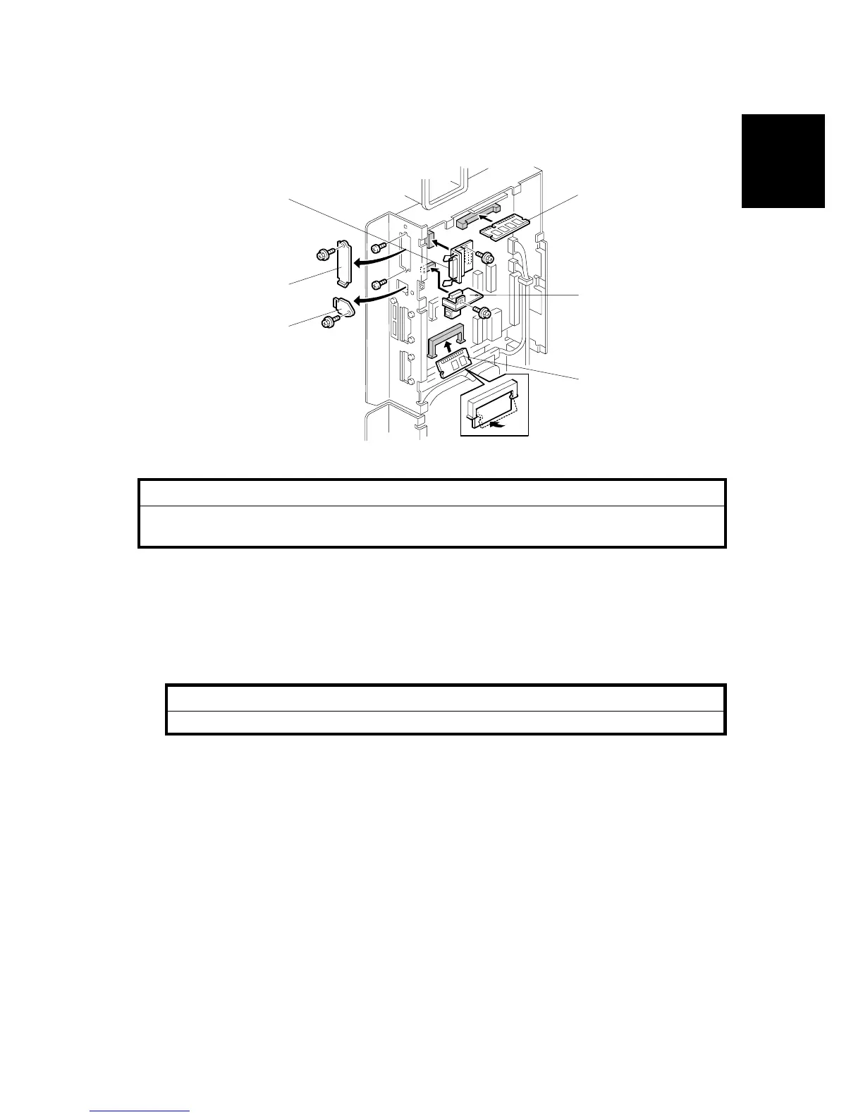
4. Insert the SDRAM DIMM (expansion memory 128 MB or 256 MB) [A] into
PC133 on the controller.
5. Insert the ROM DIMM [B] (printer/scanner) board into Slot 1.
6. Remove the Centronics connector cover [C] and insert the Centronics
connector [D] into CN310 and fasten with the provided screws ( x 2).
Rating voltage of interface connectors: Max. DC 5V
7. Remove the slot covers [E] ( x 2).
8. Install the NIB [F] into CN311 ( x 1).
Rating voltage of interface connectors: Max. DC 5V
G338I201.WMF
[A]
[B]
[D]
[F]
[C]
[E]
 Loading...