DETAILS
SM 43 B478/B513/B531
Finisher/
Jogger Unit/
Punch Unit
B478/B513/
B531
6.11 PUNCH UNIT B531 (OPTION)
6.11.1 PUNCH UNIT DRIVE
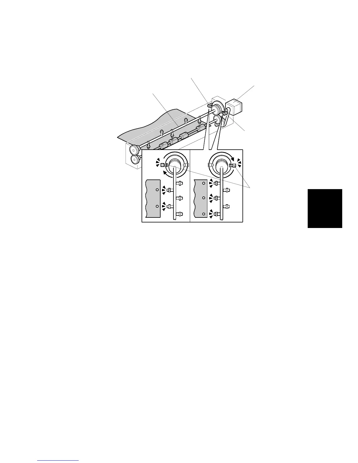
The punch unit makes 2 or 3 holes at the trailing edge of the paper. The number of
holes depends on a selection made on the operation panel.
The cam [A] has 2 punches on one side and 3 punches on the other, and is turned
by the punch motor [B]. The punch motor turns on immediately after the trailing
edge of the paper passes the entrance sensor. The punches on the cam rotate
downward and punch holes in the paper.
After punching a sheet of paper, the cam returns to home position and stops.
Home position depends on whether 2 holes or 3 holes are being made, so there
are two punch HP sensors. Punch HP sensor 1 [C] is used when 2-hole punching
is selected, and punch HP sensor 2 [D] is used when 3-hole punching is selected.
When the cut-out [E] enters the slot of the punch HP in use (sensor 1 or 2-hole
punching or sensor 2 for 3/4-hole punching) the motor stops.
The knob (not shown) on the front end of the punch unit can be turned in either
direction to clear paper jammed in the punch unit.
B531D102.WMF
[A]
[B]
[C]
[D]
[E]
 Loading...