BOARD STRUCTURE
SM 6-7 B064 Series/B140 Series/G126
Detailed
Descriptions
6.2.2 COMPONENT DESCRIPTIONS
This machine employs Ricoh RA2K architecture.
Here is a summary of the main parts of the board structure.
BCU (Base Engine Control Unit)
This is the main control board that controls engine sequence, timing for
peripherals, image processing, and the video data path.
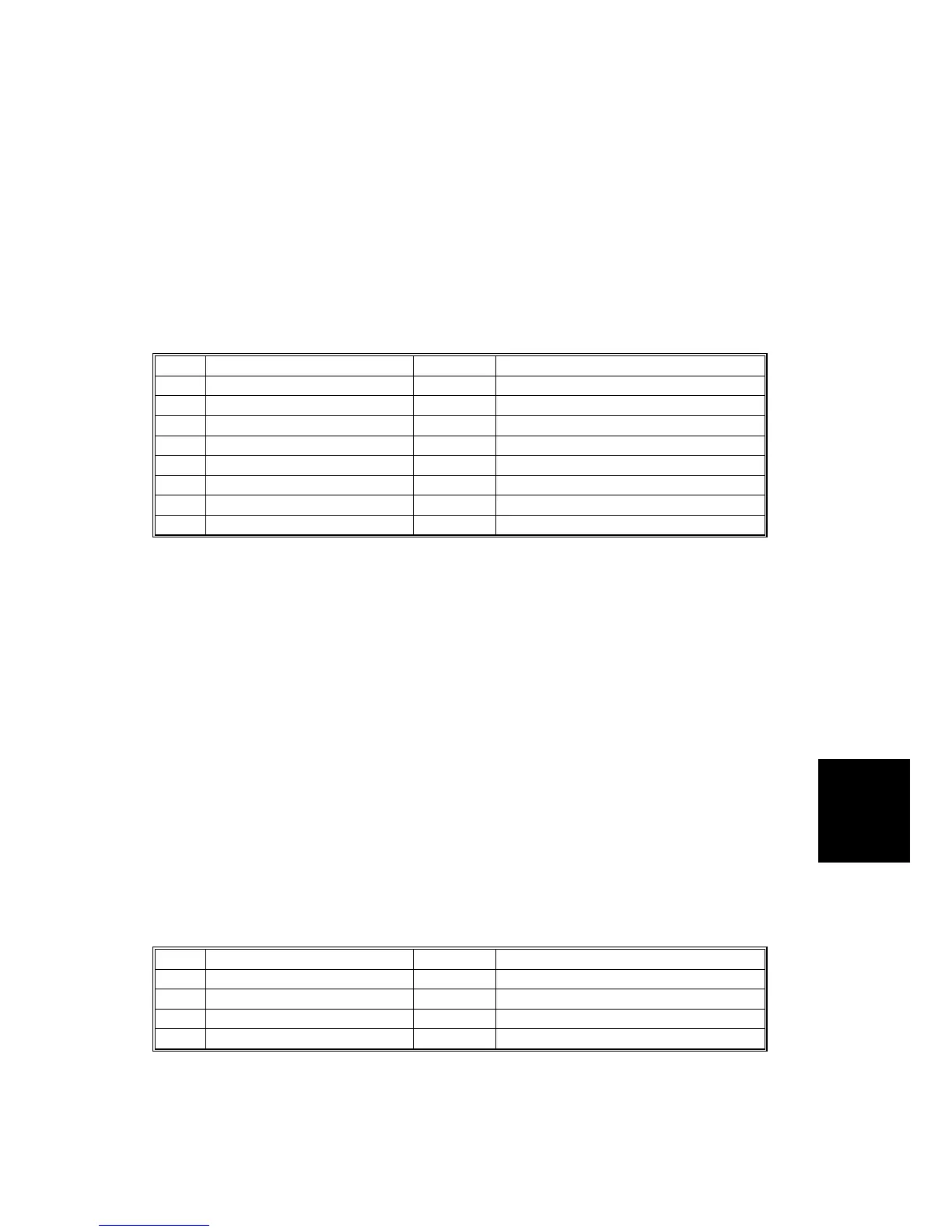
BCU Base Board DIP SW101
No. Function On/Off Comment
1 Not used OFF
2 Not used OFF
3 Design/Factory Use Only OFF
4 Not used OFF
5 Not used OFF
6 Local OFF Japan 6,7,8: OFF, OFF, OFF
7 Local OFF 115 V 6,7,8: ON, OFF, OFF
8 Local OFF 220/240V 6,7,8: OFF, ON, OFF
Controller Board
The controller controls all devices for memory DIMMs, HDD, copying, printing,
scanning, etc. In order to add an option (printer, scanner, FireWire, wireless LAN,
etc.), install the appropriate ROM DIMM on the controller board.
NOTE:
1) The Controller is on the front side of the swing out circuit board unit, with
the IPU on the back side.
2) All Controller DIP SWs should be OFF during normal operation.
MB (Mother Board)
Interfaces the Controller, BICU, and optional devices such as key counters.
IPU (Image Processing Unit)
Processes images scanned by the CIS and SBU.
All IPU Board DIP switches should be set to OFF.
IPU Board DIP SW 102
No. Function On\OFF Comment
1 DFU OFF
2 DFU OFF
3 DFU OFF
4 DFU OFF
DFU: Design, Factory Use only. Do not change these settings.
NOTE: The IPU is on the back side of the swing out circuit board unit.

 Loading...

