INPUT/OUTPUT CHECK
B064 Series/B140 Series/G126 5-162 SM
5.7 INPUT/OUTPUT CHECK
5.7.1 COPIER INPUT CHECK: SP5803
This procedure allows you to test sensors and other components of the machine.
After you select one of the categories below by number, you will see a small 8-bit
table with the number of the bit and its current setting (0 or 1). The bits are
numbered 0 to 7, reading right to left.
1. Enter the SP mode and select SP5803.
2. Enter the number (1 to 13) for the item that you want to check. A small box will
be displayed on the SP mode screen with a series of 0’s and 1’s.
The meaning of the display is as follows.
Bit 7 6 5 4 3 2 1 0
Setting
1 1 0 0 1 0 1 0
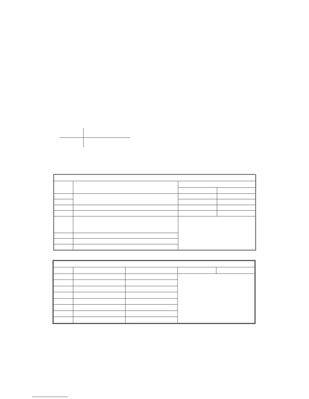
3. Check the status of each item against the corresponding bit numbers listed in
the table below.
1. Paper Feed 1
Bit Description Reading
0 1
7 Activated Deactivated
6
Rear Side Fence Close Sensor
Rear Side Fence Open Sensor
Activated Deactivated
5 Front Side Fence Close Sensor Activated Deactivated
4 Front Side Fence Open Sensor Activated Deactivated
3 Near End Sensor
(see tables below)
2 Paper Height 1 Sensor
1 Paper Height 2 Sensor
0 Paper Height 3 Sensor
2. Paper Feed 2
Bit Item 0 1
7 Size 5 Tray 2
6 Size 4 Tray 2
5 Size 3 Tray 2
4 Size 2 Tray 2
3 Size 1 Tray 2
2 Not used
1 Not used
0 Not used
See Paper Size Tables Below
 Loading...