1A-44 Engine General Information and Diagnosis:
C14 (Use of mode select switch)
Step Action Yes No
1 1) Turn the ignition switch OFF.
2) Lift and support the fuel tank. Refer to “Fuel Tank
Removal and Installation” in Section 1G (Page 1G-9).
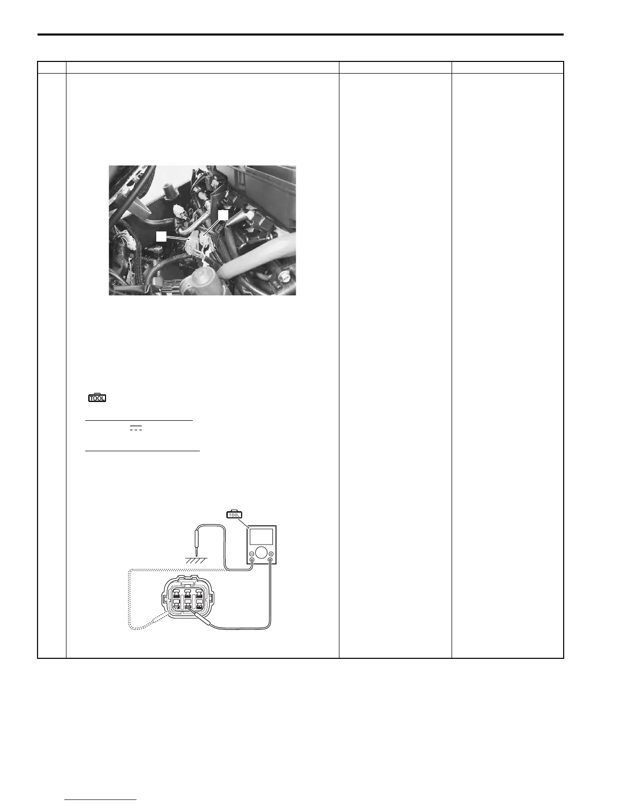
3) Check the TP sensor couplers (1) and (2) for loose or
poor contacts.
If OK, then measure the TP sensor input voltage.
4) Disconnect the TP sensor coupler (1).
5) Turn the ignition switch ON.
6) Measure the input voltage between the R wire and
ground. Also, measure the voltage between the R wire
and B/Br wire.
Special tool
(A): 09900–25008 (Multi circuit tester set)
Tester knob indication
Voltage ( )
TP sensor input voltage
4.5 – 5.5 V
((+) terminal: R – (–) terminal: Ground, (+) terminal: R
– (–) terminal: B/Br)
Is the voltage OK?
Go to Step 3. • Loose or poor
contacts on the ECM
coupler.
• Open or short circuit
in the R wire or B/Br
wire.
1
2
I947H1110021-02
V
(A)
I947H1110045-01
Manuals by Motomatrix / The Solution For Lost Motorcycle Coded Keys
email: info@motomatrix.co.uk / www.motomatrix.co.uk

 Loading...


