Combination Meter / Fuel Meter / Horn: 9C-6
Installation
Install the speed sensor in the reverse order of removal.
Pay attention to the following points:
• Tighten the speed sensor mounting bolt (1) to the
specified torque.
Tightening torque
Speed sensor mounting bolt (a): 6.5 N·m (0.65
kgf-m, 4.5 lbf-ft)
• Route the speed sensor lead wire. Refer to “Wiring
Harness Routing Diagram” in Section 9A (Page 9A-7).
Speed Sensor Inspection
B947H19306011
Inspect the speed sensor in the following procedures:
1) Remove the speed sensor. Refer to “Speed Sensor
Removal and Installation” (Page 9C-5).
2) Connect a 12 V battery (between B and B/W), 10 kΩ
resistor (between B/R and B) and multi-circuit tester
(tester (+) probe to B and tester (–) probe to B/R) as
shown in the figure.
Special tool
: 09900–25008 (Multi circuit tester set)
Tester knob indication
Voltage ( )
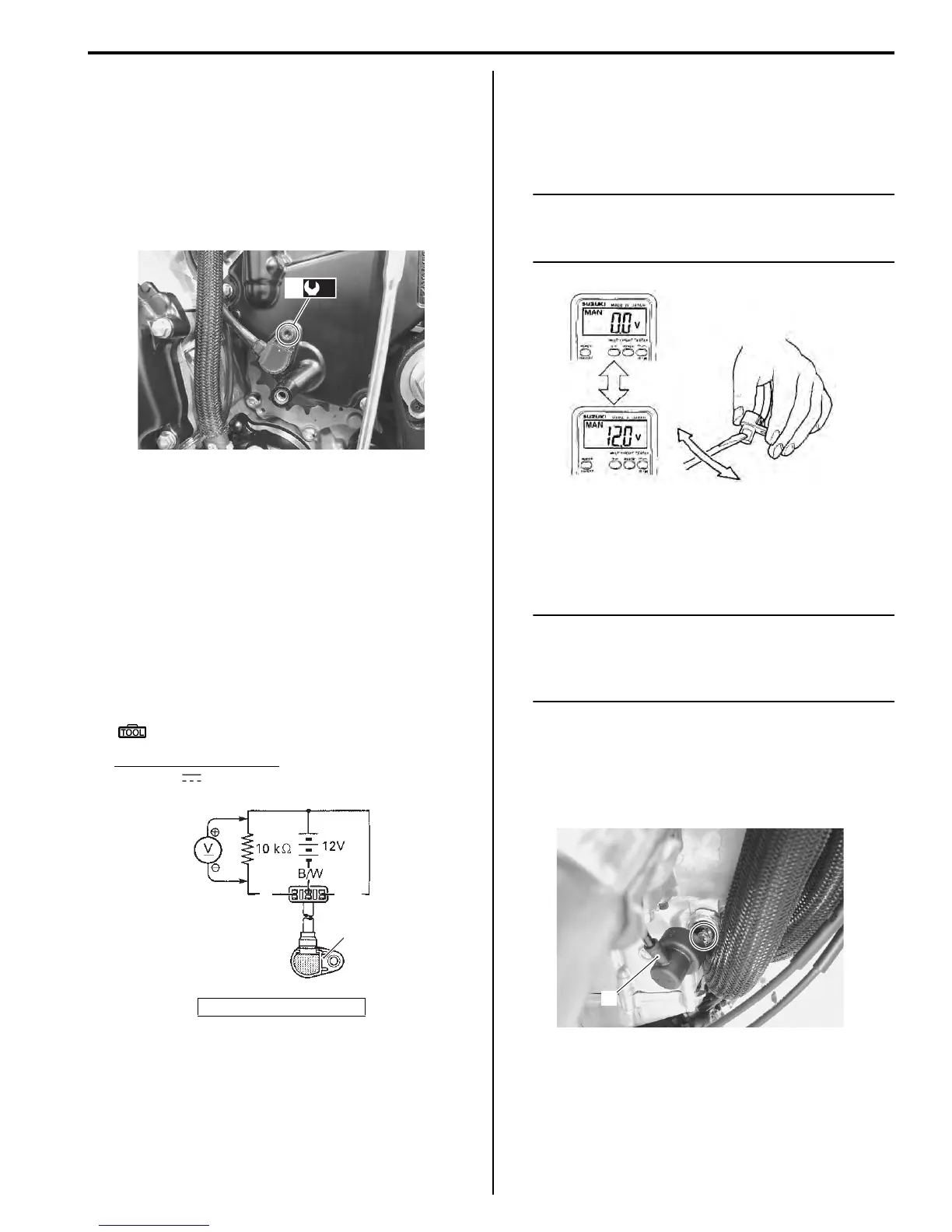
3) Move a screwdriver back and forth across the pick-
up surface of the speed sensor. The voltage
readings should cycle as follows (0 V → 12 V or 12 V
→ 0 V). If the voltage reading does not change,
replace the speed sensor with a new one.
NOTE
While testing, the highest voltage reading
should be the same as the battery voltage (12
V).
Oil Pressure Indicator Inspection
B947H19306012
Inspect the oil pressure indicator in the following
procedures:
NOTE
Before inspecting the oil pressure switch,
check if the engine oil level is correct. Refer
to “Engine Oil and Filter Replacement” in
Section 0B (Page 0B-10).
1) Remove the left side cowling. Refer to “Exterior
Parts Removal and Installation” in Section 9D
(Page 9D-6).
2) Disconnect the oil pressure switch lead wire (1) from
the oil pressure switch.
3) Turn the ignition switch ON.
1. Speed sensor
(a)
1
I947H1930014-01
B
1
B/R
I649G1930016-02
I649G1930017-02
1
I947H1930015-01
Manuals by Motomatrix / The Solution For Lost Motorcycle Coded Keys
email: info@motomatrix.co.uk / www.motomatrix.co.uk

 Loading...


