1H-9 Ignition System:
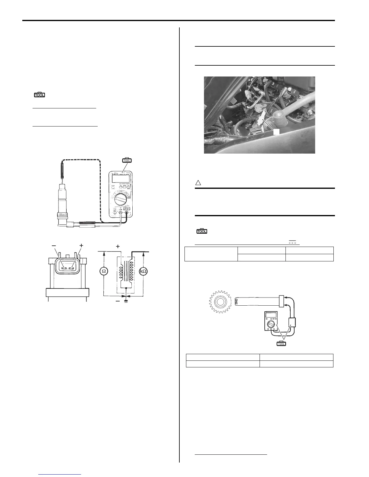
Ignition Coil Resistance
1) Remove the ignition coil. Refer to “Ignition Coil and
Spark Plug Removal and Installation” (Page 1H-6).
2) Measure the ignition coil for resistance in both
primary and secondary coils. If the resistance is not
within the standard range, replace the ignition coil
with a new one.
Special tool
(A): 09900–25008 (Multi circuit tester set)
Tester knob indication
Resistance (Ω)
Ignition coil resistance
Primary: 1.1 – 1.9 Ω ((+) terminal – (–) terminal)
Secondary: 6.4 – 9.6 kΩ (Spark plug cap – (–)
terminal)
3) After measuring the ignition coil resistance, reinstall
the removed parts.
CKP Sensor Inspection
B947H11806004
Refer to “Electrical Components Location” in Section 0A
(Page 0A-7).
CKP Sensor Peak Voltage
1) Lift and support the fuel tank. Refer to “Fuel Tank
Removal and Installation” in Section 1G (Page 1G-
9).
2) Disconnect the CKP sensor coupler (1).
NOTE
Be sure that all of the couplers are connected
properly and the battery is fully-charged.
3) Connect the multi-circuit tester with the peak volt
adaptor as follows.
CAUTION
!
Before using the multi-circuit tester and peak
voltage adaptor, refer to the appropriate
instruction manual.
Special tool
(A): 09900–25008 (Multi circuit tester set)
Tester knob indication: Voltage ( )
4) Measure the CKP sensor peak voltage in the
following procedures:
a) Shift the transmission into neutral, turn the
ignition switch ON and grasp the clutch lever.
b) Press the starter button and allow the engine to
crank for a few seconds, and then measure the
CKP sensor peak voltage.
5) Repeat the b) procedure several times and measure
the highest CKP sensor peak voltage.
CKP sensor peak voltage
0.5 V and more (B – Bl/Y)
(A)
I718H1180005-01
(ޓ)
(ޓ)
(ޓ)
(ޓ)
I718H1180006-01
CKP sensor
(+) Probe (–) Probe
BBl/Y
1. CKP sensor coupler 3. Peak voltage adaptor
2. CKP sensor
1
I947H1180011-02
Bl/Y
B
(A)
1
2
3
I947H1180020-01
Manuals by Motomatrix / The Solution For Lost Motorcycle Coded Keys
email: info@motomatrix.co.uk / www.motomatrix.co.uk

 Loading...


