Brake Control System and Diagnosis: 4A-1
Brake
Brake Control System and Diagnosis
Schematic and Routing Diagram
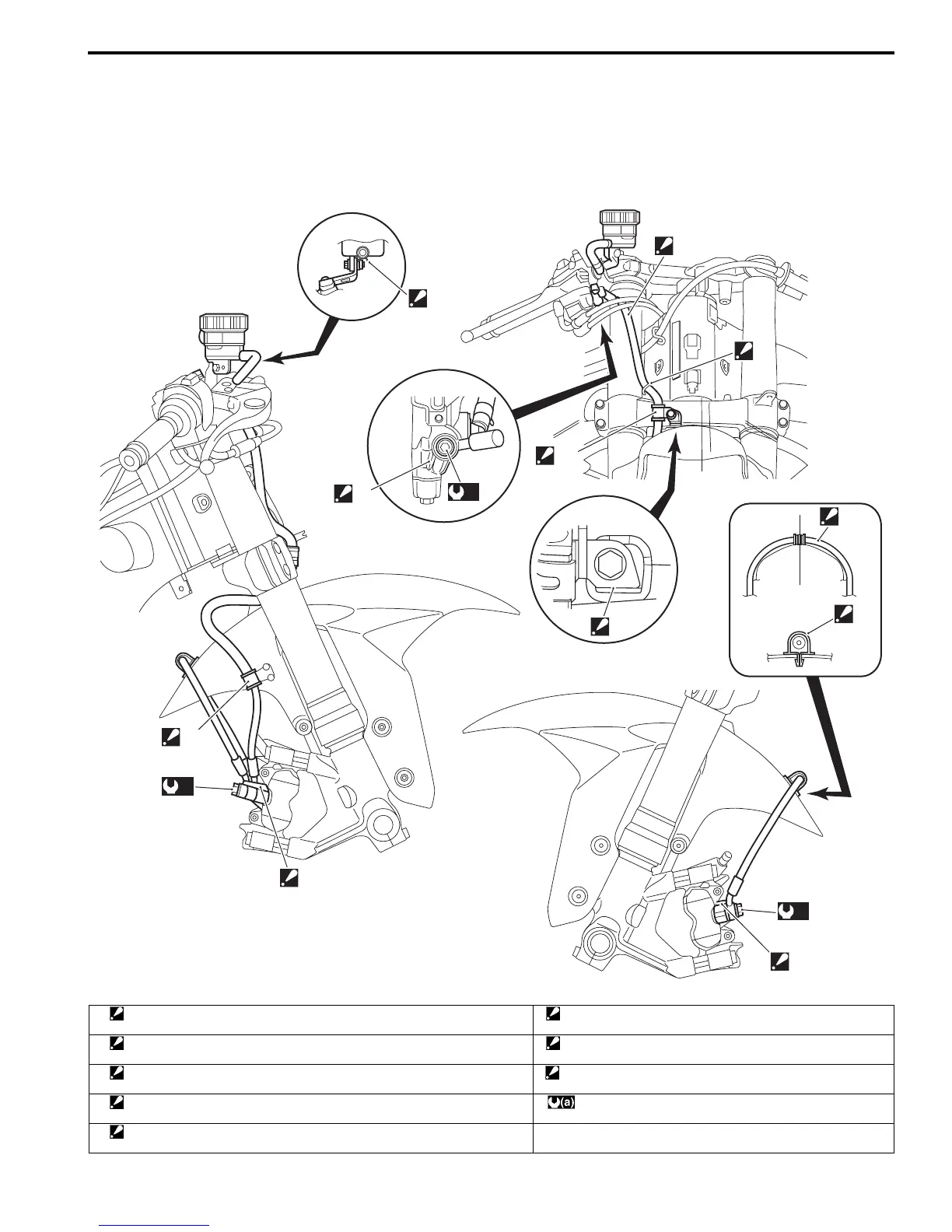
Front Brake Hose Routing Diagram
B947H14102001
1
2
2
2
3
5
“C”
4
“A”
“B”
“B”
(a)
(a)
(a)
I947H1410046-02
1. Hose clamp
: Clamp end should face downward.
“A”: White marking
: White marking should be on right side and face upward.
2. Stopper
: After the brake hose union has contacted to the stopper, tighten the union bolt.
“B”: Clamp the brake hose firmly.
3. Hose guide
: Pass the brake hose through the hose guide.
“C”: Pass the brake hose through rear side of the throttle cables.
4. Stopper
: After positioning the clamp with the stopper, tighten the clamp bolt.
:23 N⋅m (2.3 kgf-m, 16.5 lbf-ft)
5. Hose clamp
: Insert the clamp end into the hole on the front fender.
Manuals by Motomatrix / The Solution For Lost Motorcycle Coded Keys
email: info@motomatrix.co.uk / www.motomatrix.co.uk

 Loading...


