4A-2 Brake Control System and Diagnosis:
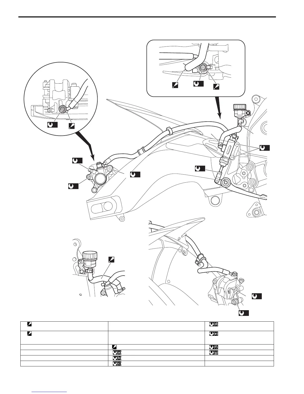
Rear Brake Hose Routing Diagram
B947H14102002
1
2
2
“A”
“B”
“C”
(c)
5
(e)
3
(d)
6
(f)
4
(a)
(e)
(g)
(a)
(b)
I947H1410047-04
1. Hose clamp
: Face the clamp end backward.
“A”: White marking : 12 N⋅m (1.2 kgf-m, 8.5 lbf-ft)
2. Stopper
: After the brake hose union has contacted
to the stopper, tighten the union bolt.
“B”: Yellow marking : 17 N⋅m (1.7 kgf-m, 12.5 lbf-ft)
3. Brake pad pin “C”: Pass the reservoir hose above the brake hose. : 2.5 N⋅m (0.25 kgf-m, 2.0 lbf-ft)
4. Plug : 23 N⋅m (2.3 kgf-m, 16.5 lbf-ft) : 6 N⋅m (0.6 kgf-m, 4.5 lbf-ft)
5. Caliper sliding pin B : 10 N⋅m (1.0 kgf-m, 7.0 lbf-ft)
6. Caliper sliding pin A : 27 N⋅m (2.7 kgf-m, 19.5 lbf-ft)
Manuals by Motomatrix / The Solution For Lost Motorcycle Coded Keys
email: info@motomatrix.co.uk / www.motomatrix.co.uk

 Loading...


