2C-9 Rear Suspension:
Cushion Rod Bearing Removal and Installation
B947H12306013
Removal
1) Remove the cushion rod. Refer to “Cushion Rod
Removal and Installation” (Page 2C-7).
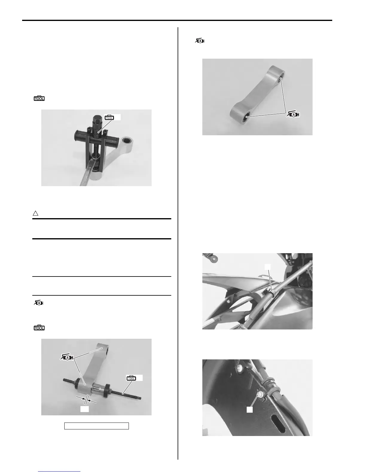
2) Remove the cushion rod bearing with the special
tool.
Special tool
(A): 09921–20240 (Bearing remover set)
Installation
CAUTION
!
The removed bearings must be replaced with
new ones.
1) Press the bearings into the cushion rod at 0.5 mm
(0.02 in) depth “a” from the cushion rod side surface
with the special tool and suitable size socket wrench.
NOTE
When installing the bearing, apply a small
quantity of the grease to housing.
: Grease 99000–25010 (SUZUKI SUPER
GREASE “A” or equivalent)
Special tool
(A): 09924–84521 (Bearing installer set)
2) Apply grease to the bearings.
: Grease 99000–25010 (SUZUKI SUPER
GREASE “A” or equivalent)
3) Install the cushion rod. Refer to “Cushion Rod
Bearing Removal and Installation” (Page 2C-9).
Swingarm Removal and Installation
B947H12306014
Removal
1) Cut the drive chain. Refer to “Drive Chain
Replacement” in Section 3A (Page 3A-7).
2) Remove the rear wheel assembly. Refer to “Rear
Wheel Assembly Removal and Installation” in
Section 2D (Page 2D-11).
3) Disconnect the rear brake hose from the brake hose
clamp (1).
4) Remove the brake hose clamp bolt (2).
5) Remove the rear brake caliper from the swingarm.
“a”: 0.5 mm (0.02 in)
(A)
I947H1230028-01
(A)
“a”
I947H1230029-02
I947H1230030-01
1
I947H1230031-01
2
I947H1230032-01
Manuals by Motomatrix / The Solution For Lost Motorcycle Coded Keys
email: info@motomatrix.co.uk / www.motomatrix.co.uk

 Loading...


