Brake Control System and Diagnosis: 4A-15
Rear Brake Master Cylinder Assembly Removal
and Installation
B947H14106016
Refer to “Rear Brake Hose Routing Diagram” (Page 4A-
2).
Removal
1) Remove the right side frame cover. Refer to “Exterior
Parts Removal and Installation” in Section 9D
(Page 9D-6).
2) Remove the rear brake fluid reservoir mounting bolt
(1).
3) Drain brake fluid. Refer to “Brake Fluid
Replacement” (Page 4A-6).
4) Place a rag underneath the brake hose union bolt (2)
on the master cylinder to catch any spilt brake fluid.
5) Remove the brake hose union bolt (2).
6) Loosen the lock-nut (3).
7) Remove the master cylinder mounting bolts (4).
8) Remove the master cylinder along with the reservoir
by turning the push rod (5).
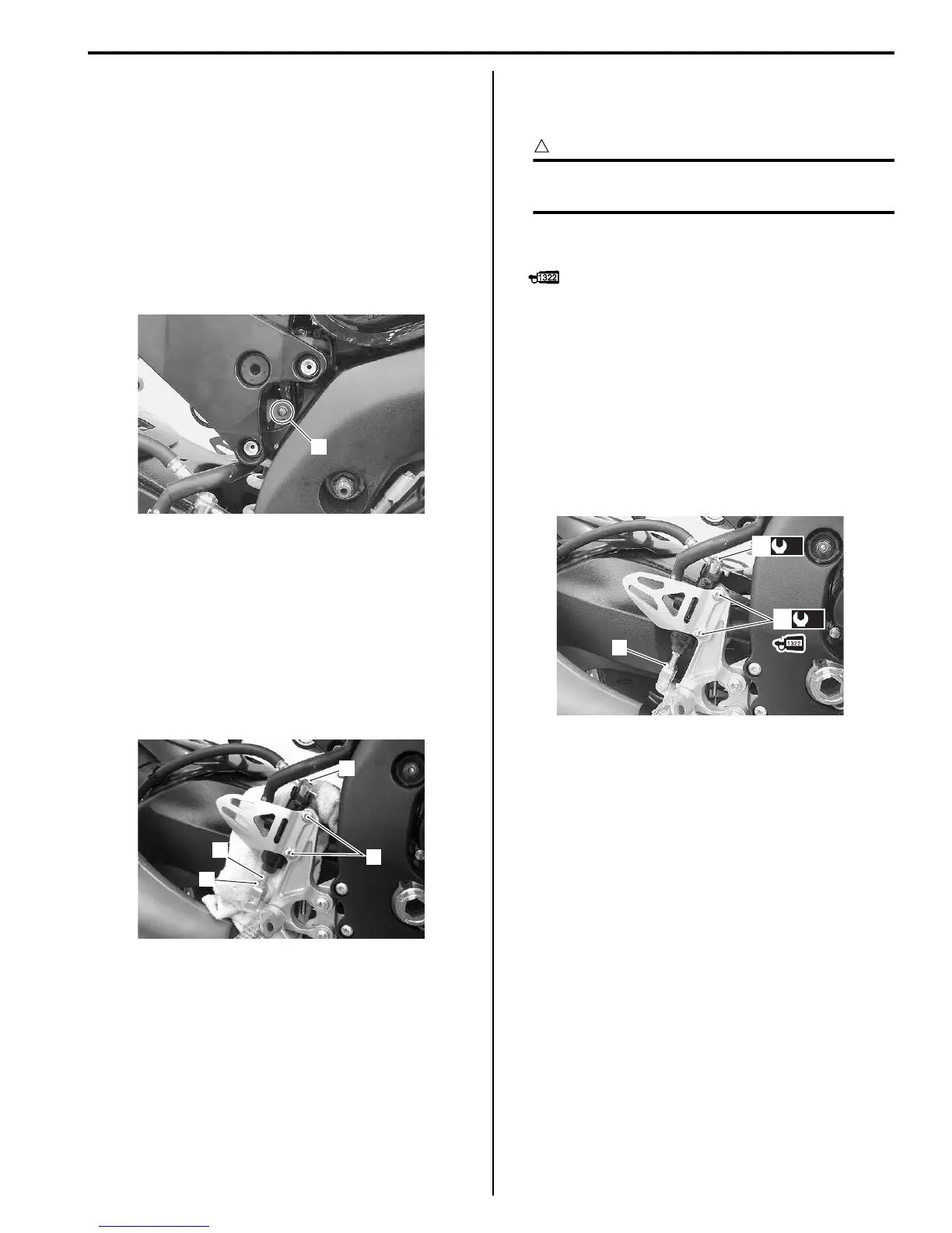
Installation
Install the rear brake master cylinder in the reverse order
of removal. Pay attention to the following points:
CAUTION
!
The seal washers should be replaced with the
new ones to prevent fluid leakage.
• Apply thread lock to the master cylinder mounting
bolts (1) and tighten them to the specified torque.
: Thread lock cement 99000–32110
(THREAD LOCK CEMENT SUPER “1322” or
equivalent)
• Tighten the lock-nut (2) temporarily.
• After setting the brake hose union to the stopper,
tighten the union bolt (3) to the specified torque.
Tightening torque
Rear brake master cylinder mounting bolt (a): 10
N·m (1.0 kgf-m, 7.0 lbf-ft)
Brake hose union bolt (b): 23 N·m (2.3 kgf-m, 16.5
lbf-ft)
• Bleed air from the brake system after reassembling
the master cylinder. Refer to “Air Bleeding from Brake
Fluid Circuit” (Page 4A-4).
• Adjust the brake pedal height. Refer to “Brake Pedal
Height Inspection and Adjustment” (Page 4A-3).
• Install the removed parts.
1
I947H1410053-01
2
3
5
4
I947H1410034-02
2
(b)
3
(a)
1
I947H1410045-02
Manuals by Motomatrix / The Solution For Lost Motorcycle Coded Keys
email: info@motomatrix.co.uk / www.motomatrix.co.uk

 Loading...


