3A-8 Drive Chain / Drive Train / Drive Shaft:
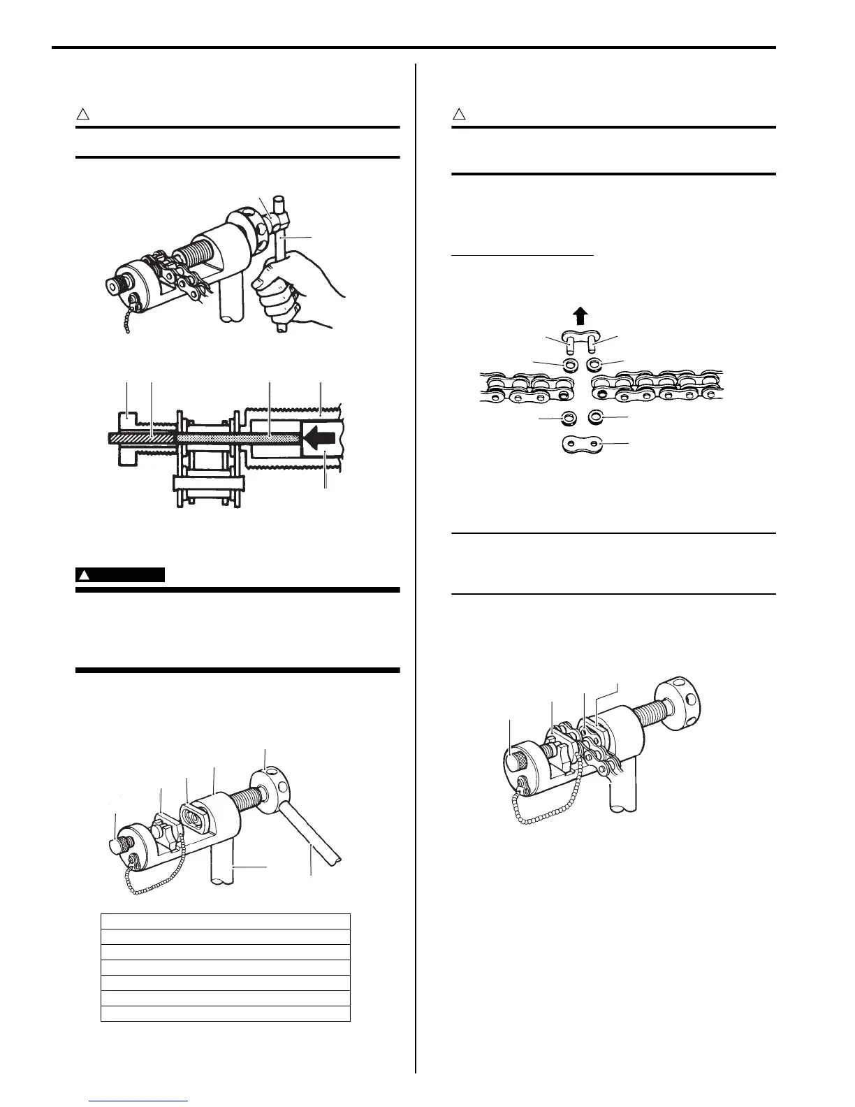
6) Remove the joint pin (9) of the other side of joint
plate.
CAUTION
!
Never reuse joint pins, O-rings and plates.
Drive Chain Connecting
WARNING
!
Do not use joint clip type of drive chain. The
joint clip may have a chance to drop which
may cause severe damage to motorcycle and
severe injury.
Joint plate installation
1) Set up the special tool as shown in the figure.
2) Apply grease to the joint pins (8), O-rings (9) and
plates (10).
CAUTION
!
Replace the joint pins (8), O-rings (9) and
plates (10) with new ones.
3) Connect both ends of the drive chain with the joint
pins (8) inserted from the wheel side “A” as installed
on the motorcycle.
Joint set part number
DID: 27620 – 40F20
4) Apply grease on the recessed portion of the joint
plate holder (3) and set the joint plate (10).
NOTE
When positioning the joint plate (10) on the
tool, its stamp mark must face the joint plate
holder (3) side.
5) Set the drive chain on the tool as illustrated and turn
in the adjuster bolt (5) to secure the wedge holder
and wedge pin (4).
6) Turn in the pressure bolt [A] (6) and align two joint
pins (8) properly with the respective holes of the joint
plate (10).
1. Tool body
2. Grip handle
3. Joint plate holder (Engraved mark “F50”)
4. Wedge holder & wedge pin
5. Adjuster bolt (Without hole)
6. Pressure bolt [A]
7. Bar
4
5
I649G1310027-02
3
4
6 7
9
I837H1310028-02
1
2
3
4
5
6
7
(F50)
I947H1310027-01
9
9
9
9
“A”
10
8
8
I837H1310029-01
3
4
5
10
I649G1310031-02
Manuals by Motomatrix / The Solution For Lost Motorcycle Coded Keys
email: info@motomatrix.co.uk / www.motomatrix.co.uk

 Loading...


