1F-3 Engine Cooling System:
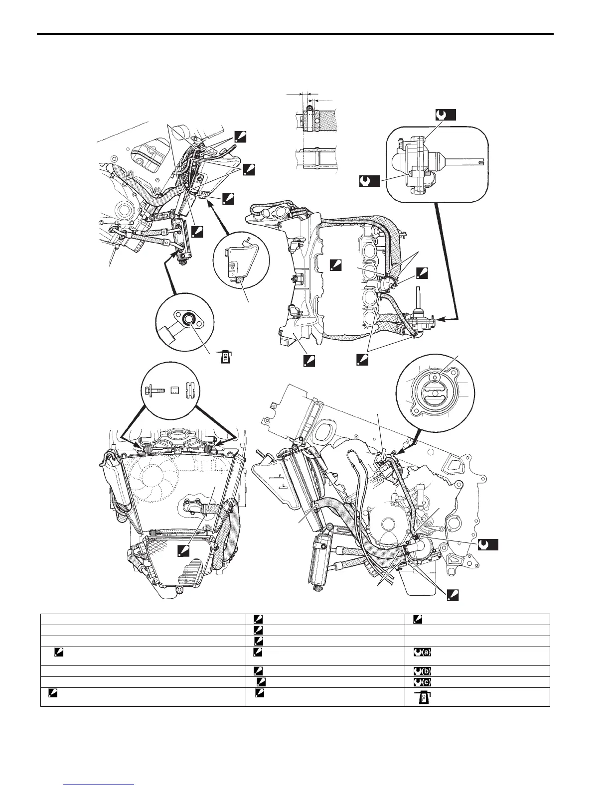
Water Hose Routing Diagram
B947H11602002
“I”
“C”
“F”
“H”
“A”
“A”
“A”
“B”
“B”
“G”
“a”
“b”
(a)
(b)
“B”
1
(c)
“K”
“A”
“J”
“D”
2
3
4
“E”
I947H1160053-03
1. Thermostat air bleeder hole “D”: Clamp end should face right side. “K”: Screw head should face left side.
2. Cushion “E”: Cut off the excess tip of the clamp. “a”: 2 – 8 mm (0.08 – 0.31 in)
3. O-ring “F”: Screw head should face right side. “b”: Clearance
4. Radiator heat guard
: Be careful not to damage the pawls when removing.
“G”: Screw head should face backward. : 6 N⋅m (0.6 kgf-m, 4.5 lbf-ft)
“A”: Yellow marking “H”: Clamp end should face upward. : 10 N⋅m (1.0 kgf-m, 0.7 lbf-ft)
“B”: White marking “I”: Clamp end should face left side. : 13 N⋅m (1.3 kgf-m, 9.5 lbf-ft)
“C”: Clamp end should face downward. “J”: Screw head should face forward. : :Apply engine oil.
Manuals by Motomatrix / The Solution For Lost Motorcycle Coded Keys
email: info@motomatrix.co.uk / www.motomatrix.co.uk

 Loading...


