9A-7 Wiring Systems:
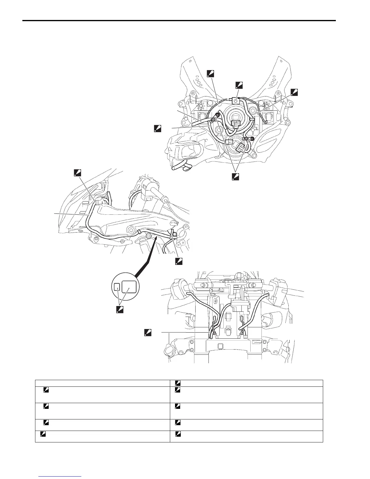
Wiring Harness Routing Diagram
B947H19102002
1
1
“C”
“D”
“F”
4
“A”, “B”
“A”
3
“E”
2
I947H1910907-03
1. Wiring harness No. 2 “B”: Pass the left position light lead wires under the wiring harness No. 2.
2. Tapping clamp
: Insert the clamp from the front side. Place the turn signal
and position light couplers in front of the clamp.
“C”: Route the steering damper lead wire under the wiring harness No. 2.
Do not pass it over the harness.
3. Steel clamp
: Clamp the wiring harness at the blue taping point. Bend
the steel clamps to the front side.
“D”: Pass the wiring harness No. 2 in front of the air intake pipe mounting
fastener.
4. Clamp:
Face the clamp end upward.
“E”: Place the small coupler inside and the big one outside.
“A”: Take care not pinch the position light lead wires between
the headlight assembly and cowling brace.
“F”: Pass the right handlebar switch lead wire above the ignition switch
lead wire.
Manuals by Motomatrix / The Solution For Lost Motorcycle Coded Keys
email: info@motomatrix.co.uk / www.motomatrix.co.uk

 Loading...


