9C-5 Combination Meter / Fuel Meter / Horn:
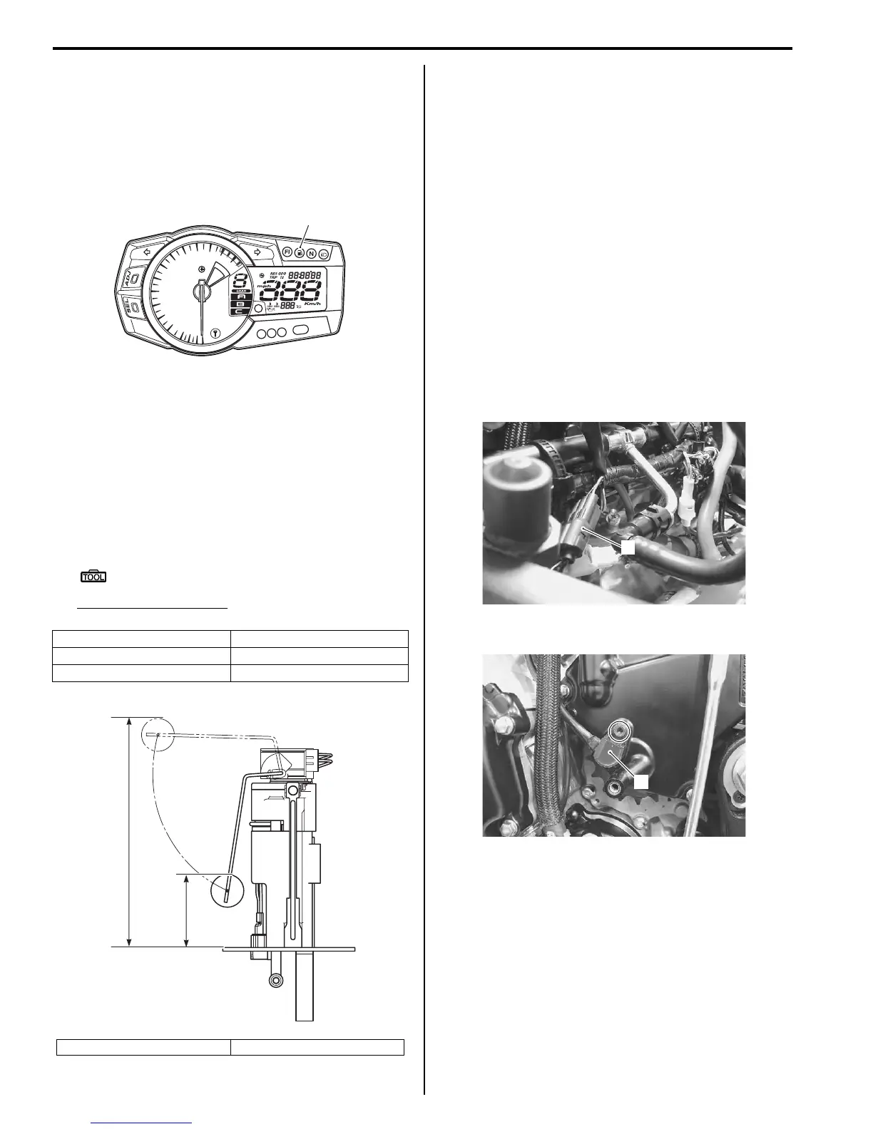
Fuel Level Indicator Inspection
B947H19306007
If the fuel level indicator light (1) does not function
properly, check the fuel level gauge and its lead wire/
coupler.
If the fuel level gauge and its lead wire/coupler are
functioning properly, replace the combination meter with
a new one.
Fuel Level Gauge Inspection
B947H19306008
Inspect the fuel level gauge in the following procedures:
1) Remove the fuel pump. Refer to “Fuel Pump
Disassembly and Assembly” in Section 1G
(Page 1G-11).
2) Measure the resistance at each fuel level gauge in
float position. If the resistance is incorrect, replace
fuel level gauge with a new one.
Special tool
: 09900–25008 (Multi circuit tester set)
Tester knob indication
Resistance (Ω)
3) Install the fuel pump. Refer to “Fuel Pump
Disassembly and Assembly” in Section 1G
(Page 1G-11).
Speedometer Inspection
B947H19306009
If the speedometer, odometer or tripmeter does not
function properly, inspect the speed sensor and the
coupler connections. If the speed sensor and coupler
connections are OK, replace the combination meter unit
with a new one. Refer to “Combination Meter Removal
and Installation” (Page 9C-2).
Speed Sensor Removal and Installation
B947H19306010
Removal
1) Remove the left side cowling. Refer to “Exterior
Parts Removal and Installation” in Section 9D
(Page 9D-6).
2) Disconnect the speed sensor lead wire coupler (1).
3) Remove the speed sensor (2).
Float position Resistance
Full “a” 3 – 5 Ω
Empty “b” 179 – 185 Ω
“a”: 186.5 ± 5 mm (3.34 ± 0.2 in) “b”: 59.7 ± 5 mm (2.35 ± 0.2 in)
1
I947H1930010-01
“a”
“b”
I947H1930011-01
1
I947H1930012-01
2
I947H1930013-01
Manuals by Motomatrix / The Solution For Lost Motorcycle Coded Keys
email: info@motomatrix.co.uk / www.motomatrix.co.uk

 Loading...


