Emission Control Devices: 1B-9
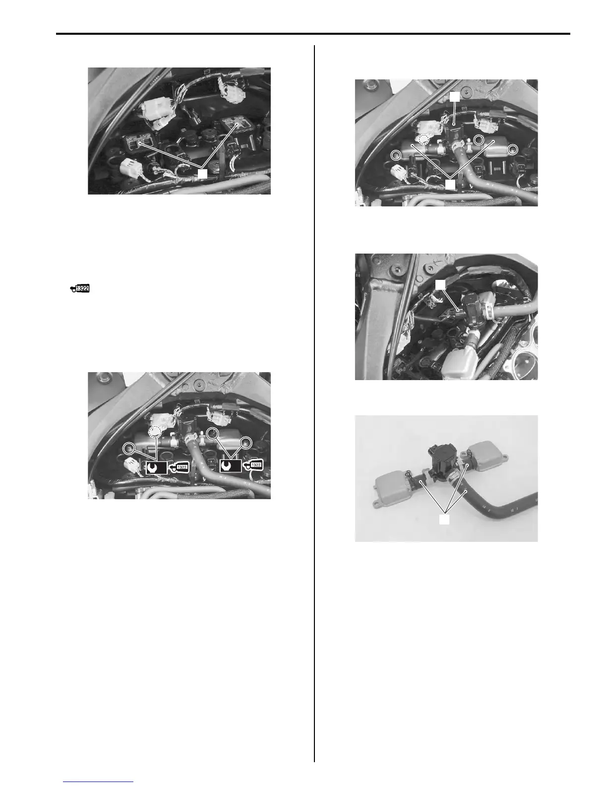
4) Remove the PAIR reed valves (3).
Installation
Install the PAIR reed valve in the reverse order of
removal. Pay attention to the following points:
• Apply thread lock to the PAIR reed valve cover bolts
and tighten them to the specified torque.
: Thread lock cement 99000–32110
(THREAD LOCK CEMENT SUPER “1322” or
equivalent)
Tightening torque
PAIR reed valve cover bolt (a): 10 N·m (1.0 kgf-m,
7.0 lbf-ft)
PAIR Control Solenoid Valve Removal and
Installation
B947H11206004
Removal
1) Lift and support the fuel tank with the prop stay.
Refer to “Fuel Tank Removal and Installation” in
Section 1G (Page 1G-9).
2) Remove the air cleaner box. Refer to “Air Cleaner
Box Removal and Installation” in Section 1D
(Page 1D-7).
3) Remove the PAIR control solenoid valve (1) along
with the PAIR reed valve covers (2).
4) Disconnect the PAIR control solenoid valve coupler
(3).
5) Disconnect the PAIR hoses (4).
Installation
Install the PAIR control solenoid valve in the reverse
order of removal. Pay attention to the following point:
• Connect the PAIR hoses properly. Refer to “PAIR
System Hose Routing Diagram” (Page 1B-6).
PAIR System Inspection
B947H11206005
PAIR Hose
1) Lift and support the fuel tank with the prop stay.
Refer to “Fuel Tank Removal and Installation” in
Section 1G (Page 1G-9).
2) Remove the air cleaner box. Refer to “Air Cleaner
Box Removal and Installation” in Section 1D
(Page 1D-7).
3
I947H1120013-01
(a)
(a)
I947H1120014-02
1
2
I947H1120015-02
3
I947H1120016-02
4
I947H1120042-01
Manuals by Motomatrix / The Solution For Lost Motorcycle Coded Keys
email: info@motomatrix.co.uk / www.motomatrix.co.uk

 Loading...


