1D-78 Engine Mechanical:
Conrod Crank Pin Bearing Inspection and
Selection
B947H11406042
Refer to “Engine Bottom Side Disassembly” (Page 1D-
49).
Refer to “Engine Bottom Side Assembly” (Page 1D-56).
Inspection
1) Inspect the bearing surfaces for any signs of fusion,
pitting, burn or flaws. If any, replace them with a
specified set of bearings.
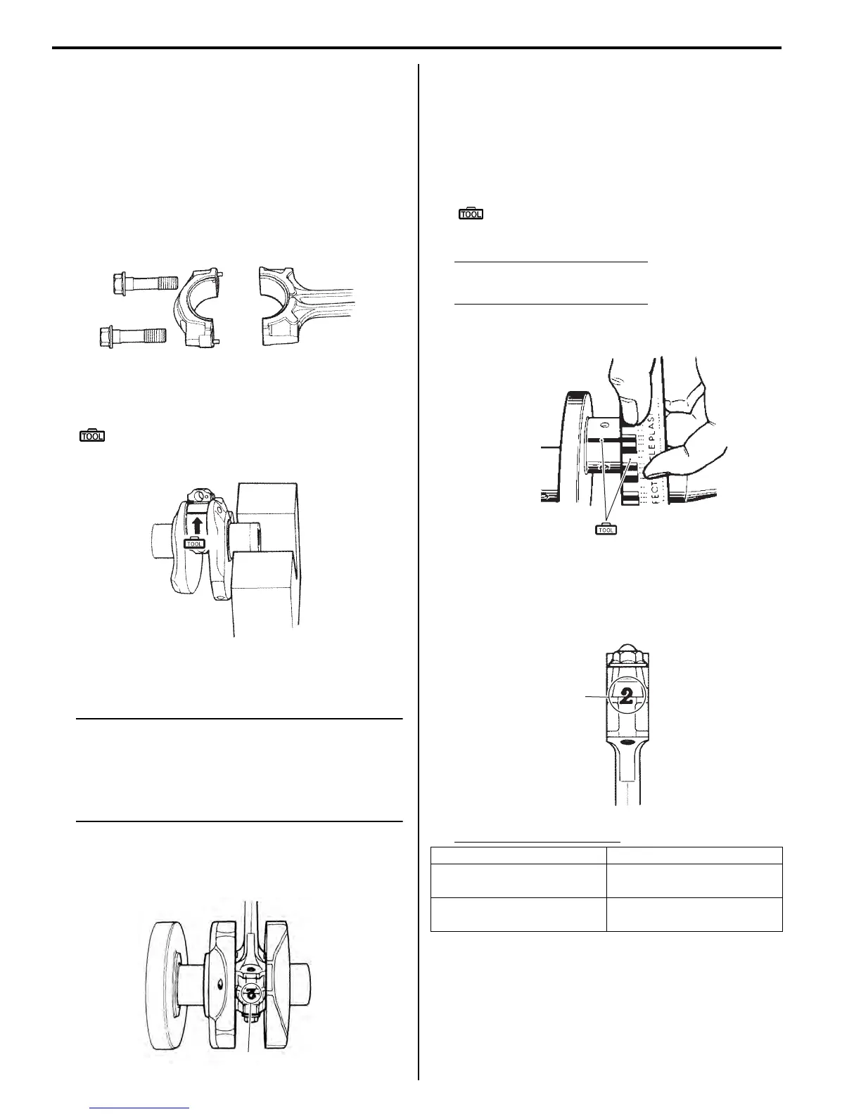
2) Place the plastigauge axially along the crank pin,
avoiding the oil hole, as shown in the figure.
Special tool
(A): 09900–22301 (Plastigage (0.025 – 0.076
mm))
3) Tighten the conrod cap bolts to the specified torque,
in two stages.
NOTE
• When installing the conrod cap bolts to the
crank pin, make sure that I.D code “A” on
the conrod faces towards the intake side.
• Never rotate the crankshaft or conrod
when a piece of plastigauge is installed.
Tightening torque
Conrod cap bolt: 37 N⋅m (3.7 kgf-m, 26.5 Ib-ft)
then turn in 1/6 (60°) turn
4) Remove the conrod cap bolts and measure the width
of the compressed plastigauge using the envelope
scale. This measurement should be taken at the
widest part of the compressed plastigauge.
If the oil clearance exceeds the service limit, select
the specified bearings from the bearing selection
table.
Special tool
(A): 09900–22301 (Plastigage (0.025 – 0.076
mm))
Conrod big end oil clearance
Standard: 0.040 – 0.064 mm (0.0016 – 0.0025 in)
Conrod big end oil clearance
Service limit: 0.080 mm (0.0031 in)
Selection
1) Check the corresponding conrod I.D. code numbers
([1] or [2]) “A”.
Conrod I.D. specification
I718H1140285-01
(A)
I718H1140286-01
“A”
I823H1140284-01
Code “A” I.D. specification
1
38.000 – 38.008 mm
(1.4961 – 1.4964 in)
2
38.008 – 38.016 mm
(1.4964 – 1.4967 in)
(A)
I718H1140289-01
“A”
I718H1140290-01
Manuals by Motomatrix / The Solution For Lost Motorcycle Coded Keys
email: info@motomatrix.co.uk / www.motomatrix.co.uk

 Loading...


