1B-6 Emission Control Devices:
Schematic and Routing Diagram
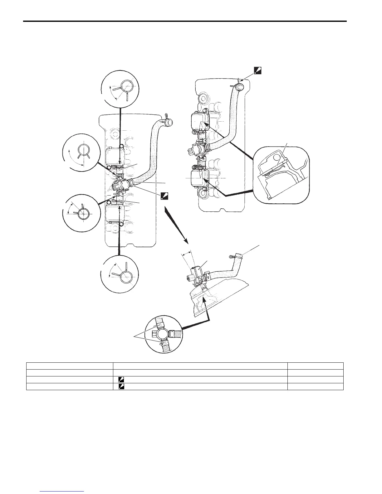
PAIR System Hose Routing Diagram
B947H11202001
1
2
“C”
“D”
“E”
“B”
“B”
“b”
“a”
“b”
“b”
“c”
“F”
“A”
I947H1120006-03
1. PAIR control solenoid valve “C”: Blue marking “a”: 90°
2. PAIR reed valve “D”: Red marking “b”: 45°
“A”: White marking (hidden side) “E”: Face the clamp end to the top. “c”: 15°
“B”: Yellow marking “F”: Make sure the clamp is not contacted to the frame or air cleaner box.
Manuals by Motomatrix / The Solution For Lost Motorcycle Coded Keys
email: info@motomatrix.co.uk / www.motomatrix.co.uk

 Loading...


