Brake Control System and Diagnosis: 4A-11
• After setting the brake hose union to the stopper,
tighten the union bolt (2) to the specified torque.
CAUTION
!
The seal washers should be replaced with the
new ones to prevent fluid leakage.
Tightening torque
Brake hose union bolt (b): 23 N·m (2.3 kgf-m, 16.5
lbf-ft)
• Bleed air from the master cylinder in the same manner
as caliper side.
NOTE
If air is trapped in the master cylinder, bleed
air from the master cylinder first.
Tightening torque
Air bleeder valve (Front master cylinder): 6 N·m (
0.6 kgf-m, 4.5 lbf-ft)
• Bleed air from brake system. Refer to “Air Bleeding
from Brake Fluid Circuit” (Page 4A-4).
Front Brake Master Cylinder / Brake Lever
Disassembly and Assembly
B947H14106013
Refer to “Front Brake Master Cylinder Assembly
Removal and Installation” (Page 4A-10).
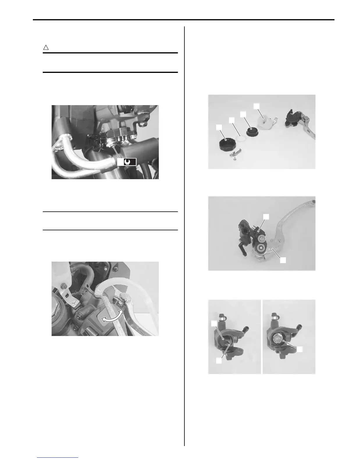
Disassembly
1) Remove the reservoir cap (1), PLATE (2), diaphragm
(3) and reservoir tank (4).
2) Remove the brake light switch (5) and brake lever
(6).
3) Remove the dust boot (7) and push rod (8).
4) Remove the snap ring (9).
(b)
2
I947H1410021-03
I947H1410022-01
1
2
3
4
I947H1410023-01
5
6
I947H1410024-01
7
8
9
I947H1410025-02
Manuals by Motomatrix / The Solution For Lost Motorcycle Coded Keys
email: info@motomatrix.co.uk / www.motomatrix.co.uk

 Loading...


