Engine Mechanical: 1D-75
Balancer Shaft Journal Bearing Inspection and
Selection
B947H11406039
Refer to “Engine Bottom Side Disassembly” (Page 1D-
49).
Refer to “Engine Bottom Side Assembly” (Page 1D-56).
Inspection
Inspect the bearing surfaces for any signs of fusion,
pitting, burn or flaws. If any, replace them with a
specified set of bearings.
Selection
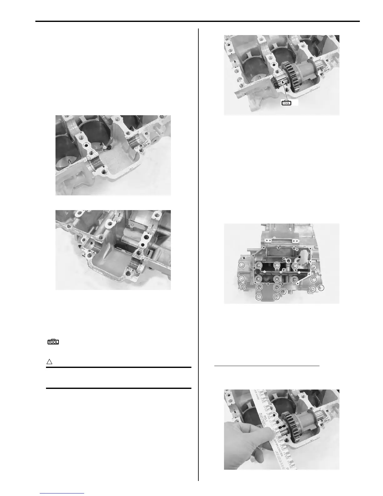
1) Place the plastigauge axially along the balancer
shaft journal as shown.
Special tool
(A): 09900–22301 (Plastigage (0.025 – 0.076
mm))
CAUTION
!
Never rotate the balancer shaft when a piece
of plastigauge is installed.
2) Mate the lower crankcase with the upper crankcase,
and tighten the crankcase bolts (M8) and crankshaft
journal bolts (M9) to the specified torque.
Tightening torque
Crankshaft journal bolt (M9): 18 N⋅m (1.8 kgf-m,
13.0 lbf-ft) then turn in 50°
Crankcase bolt (M8) (Initial): 15 N·m (1.5 kgf-m,
11.0 lbf-ft)
Crankcase bolt (M8) (Final): 26 N·m (2.6 kgf-m,
19.0 lbf-ft)
Crankcase bolt (M6): 12 N·m (1.2 kgf-m, 8.5 lbf-
ft)
3) Remove the lower crankcase and measure the width
of the compressed plastigauge using the envelope
scale. This measurement should be taken at the
widest part of the compressed plastigauge. If the oil
clearance exceeds the service limit, select the
specified bearings from the bearing selection table.
Balancer shaft journal oil clearance
Standard: 0.028 – 0.052 mm (0.0011 – 0.0020 in)
Service limit: 0.080 mm (0.0031 in)
I947H1140228-02
I947H1140229-01
(A)
I947H1140230-01
I947H1140231-01
I947H1140232-01
Manuals by Motomatrix / The Solution For Lost Motorcycle Coded Keys
email: info@motomatrix.co.uk / www.motomatrix.co.uk

 Loading...


