Drive Chain / Drive Train / Drive Shaft: 3A-3
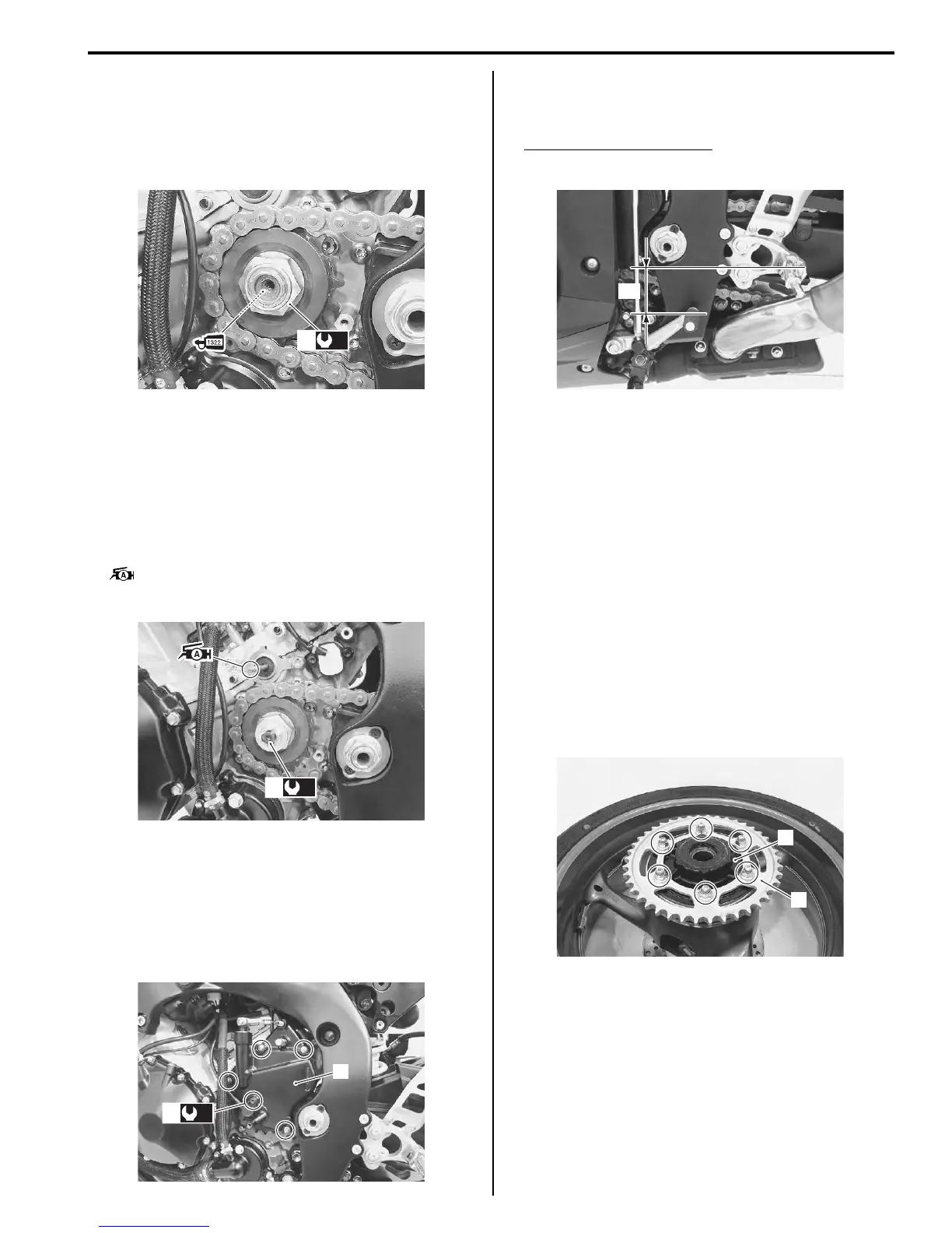
• Tighten the engine sprocket nut (1) to the specified
torque.
Tightening torque
Engine sprocket nut (a): 145 N·m (14.5 kgf-m,
105.0 lbf-ft)
• Tighten the speed sensor rotor bolt (2) to the specified
torque.
Tightening torque
Speed sensor rotor bolt (b): 28 N·m (2.8 kgf-m,
20.0 lbf-ft)
• Before installing the engine sprocket cover, apply a
small quantity of grease to the clutch push rod.
: Grease 99000–25010 (SUZUKI SUPER
GREASE “A” or equivalent)
• Install the engine sprocket cover (3).
• Tighten the speed sensor mounting bolt (4) to the
specified torque.
Tightening torque
Speed sensor mounting bolt (c): 6.5 N·m (0.65
kgf-m, 4.5 lbf-ft)
• Fit the gearshift link arm to the gearshift shaft so that
the gearshift lever is located at height “a” below the
footrest.
Gearshift lever height “a”
Standard: 65 – 75 mm (2.6 – 3.0 in)
• Adjust the drive chain slack. Refer to “Drive Chain
Inspection and Adjustment” in Section 0B (Page 0B-
14).
Rear Sprocket / Rear Sprocket Mounting Drum
Removal and Installation
B947H13106003
Removal
1) Remove the rear wheel assembly. Refer to “Rear
Wheel Assembly Removal and Installation” in
Section 2D (Page 2D-11).
2) Loosen the rear sprocket nuts.
3) Draw out the rear sprocket mounting drum (1) along
with the rear sprocket (2) from the wheel hub.
4) Remove the rear sprocket nuts and separate the
rear sprocket (2) from its mounting drum (1).
(a)
1
I947H1310024-01
(b)
2
I947H1310025-01
(c)
4
3
I947H1310026-01
“a”
I947H1310001-01
1
2
I947H1310002-01
Manuals by Motomatrix / The Solution For Lost Motorcycle Coded Keys
email: info@motomatrix.co.uk / www.motomatrix.co.uk

 Loading...


