5B-14 Manual Transmission:
Gear Position (GP) Switch Removal and
Installation
B947H15206008
Removal
1) Turn the ignition switch OFF.
2) Lift and support the fuel tank. Refer to “Fuel Tank
Removal and Installation” in Section 1G (Page 1G-
9).
3) Disconnect the gear position switch lead wire
coupler (1).
4) Remove the engine sprocket cover. Refer to “Engine
Sprocket Removal and Installation” in Section 3A
(Page 3A-2).
5) Remove the GP switch (2).
Installation
Install the gear position switch in the reverse order of
removal. Pay attention to the following points:
• Apply grease to the O-ring.
CAUTION
!
Replace the O-ring with a new one.
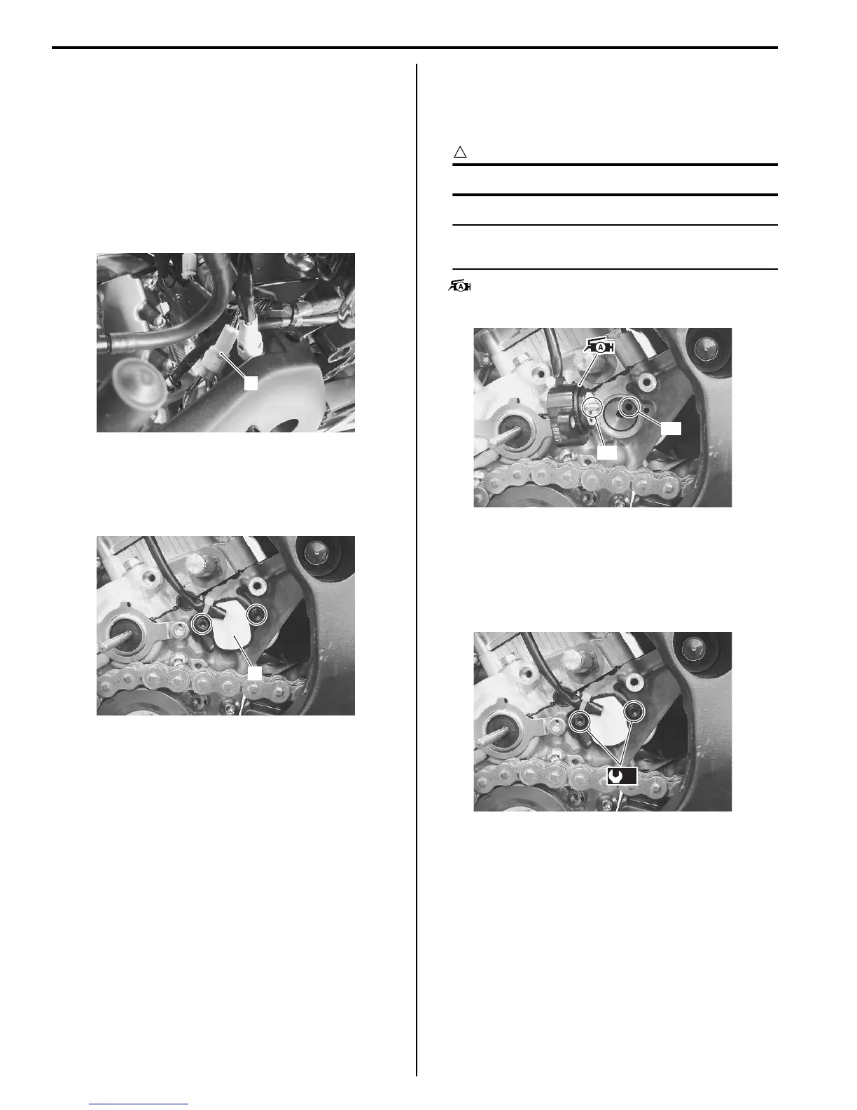
NOTE
Align the gear position switch pin “A” with
the gearshift cam hole “B”.
: Grease 99000–25010 (SUZUKI SUPER
GREASE “A” or equivalent)
• Tighten the gear position switch mounting bolts to the
specified torque.
Tightening torque
Gear position switch mounting bolt (a): 6.5 N·m (
0.65 kgf-m, 4.5 lbf-ft)
• Route the gear position switch lead wire. Refer to
“Wiring Harness Routing Diagram” in Section 9A
(Page 9A-7).
1
I947H1520068-01
2
I947H1520069-01
“A”
“B”
I947H1520070-01
(a)
I947H1520071-01
Manuals by Motomatrix / The Solution For Lost Motorcycle Coded Keys
email: info@motomatrix.co.uk / www.motomatrix.co.uk

 Loading...


