Engine General Information and Diagnosis: 1A-99
Troubleshooting
CAUTION
!
When using the multi-circuit tester, do not strongly touch the terminal of the ECM coupler with a
needle pointed tester probe to prevent terminal damage.
NOTE
After repairing the trouble, clear the DTC using SDS tool. Refer to “Use of SDS Diagnosis Reset
Procedures” (Page 1A-14).
C41 (Use of mode select switch)
Step Action Yes No
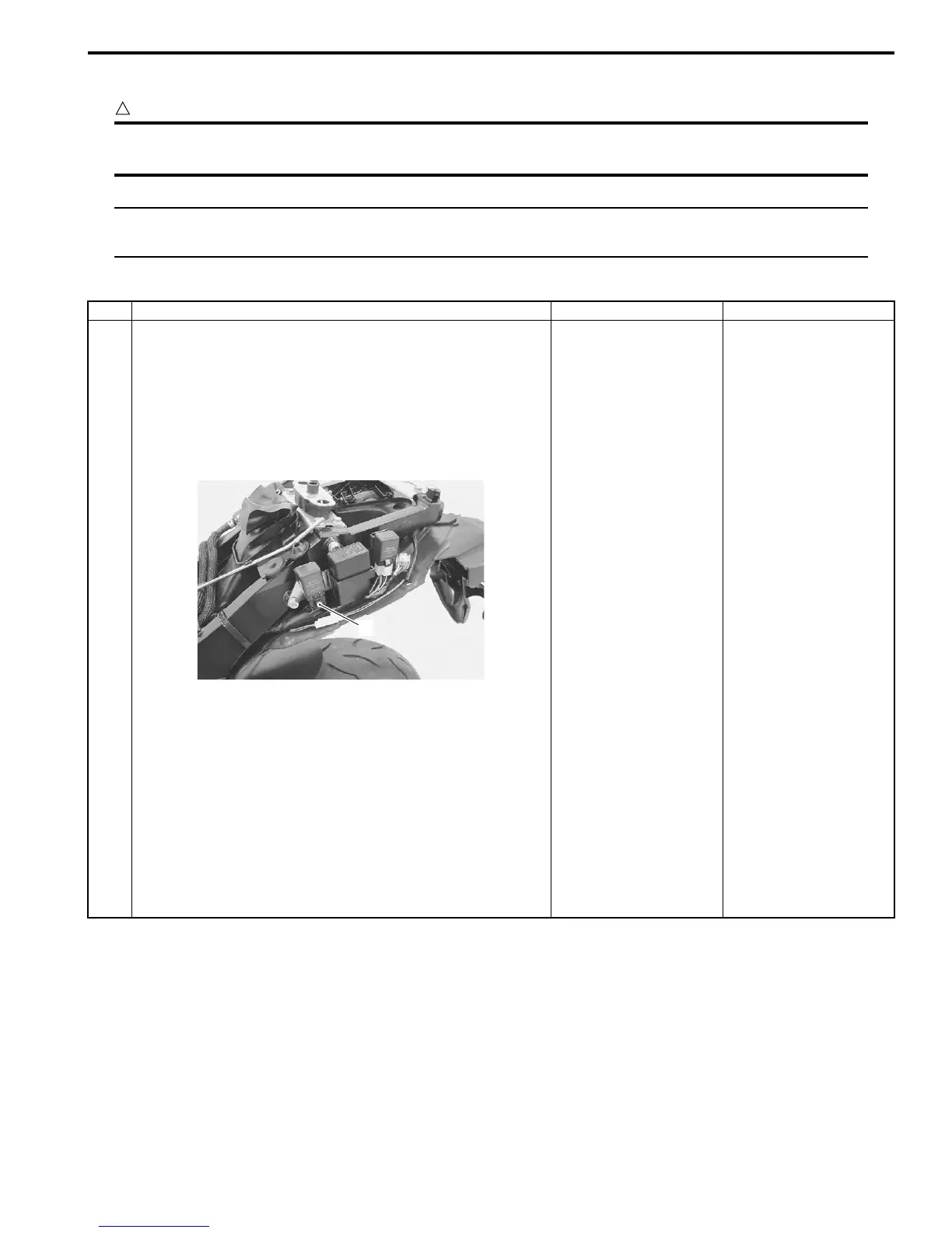
1 1) Turn the ignition switch OFF.
2) Remove the frame covers. Refer to “Exterior Parts
Removal and Installation” in Section 9D (Page 9D-6).
3) Check the FP relay coupler (1) for loose or poor
contacts.
If OK, then check the FP relay. Refer to “Fuel Pump
Relay Inspection” in Section 1G (Page 1G-7).
Is the FP relay OK?
• ECM power input
signal malfunction.
Refer to “DTC “C41”
(P2505): ECM Power
Input Signal
Malfunction”
(Page 1A-101).
• Y/B or O/W wire open
or short or poor “40”
connection.
• Y/R or R/Bl wire
open, shorted or poor
“24” connection.
• If wire and
connection are OK,
intermittent trouble or
faulty ECM.
• Recheck each
terminal and wire
harness for open
circuit and poor
connection.
• Replace the ECM
with a known good
one, and inspect it
again. Refer to “ECM
Removal and
Installation” in
Section 1C
(Page 1C-1).
Replace the FP relay
with a new one.
1
I947H1110070-01
Manuals by Motomatrix / The Solution For Lost Motorcycle Coded Keys
email: info@motomatrix.co.uk / www.motomatrix.co.uk

 Loading...


