Engine General Information and Diagnosis: 1A-25
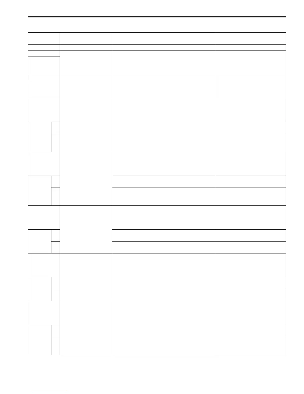
Malfunction Code and Defective Condition Table
B947H11104009
Malfunction
Code
Detected Item Detected Failure Condition Check For
C00 NO FAULT — —
C11
CMP sensor
The signal does not reach ECM for 3 sec. or
more, after receiving the starter signal.
CMP sensor wiring and
mechanical parts
CMP sensor, intake cam pin,
wiring/coupler connection
P0340
C12
CKP sensor
The signal does not reach ECM for 3 sec. or
more, after receiving the starter signal.
CKP sensor wiring and
mechanical parts
CKP sensor, lead wire/coupler
connection
P0335
C13
IAP sensor
The sensor should produce following voltage.
0.5 V ≤ Sensor voltage < 4.85 V
In other than the above range, C13 (P0105) is
indicated.
IAP sensor, lead wire/coupler
connection
P0105
H Sensor voltage is higher than specified value.
IAP sensor circuit shorted to
VCC or ground circuit open
L Sensor voltage is lower than specified value.
IAP sensor circuit open or
shorted to ground or VCC
circuit open
C14
TP sensor
The sensor should produce following voltage.
0.2 V ≤ Sensor voltage < 4.8 V
In other than the above range, C14 (P0120) is
indicated.
TP sensor, lead wire/coupler
connection
P0120
H Sensor voltage is higher than specified value.
TP sensor circuit shorted to
VCC or ground circuit open
L Sensor voltage is lower than specified value.
TP sensor circuit open or
shorted to ground or VCC
circuit open
C15
ECT sensor
The sensor voltage should be the following.
0.15 V ≤ Sensor voltage < 4.85 V
In other than the above range, C15 (P0115) is
indicated.
ECT sensor, lead wire/coupler
connection
P0115
H Sensor voltage is higher than specified value.
ECT sensor circuit open or
ground circuit open
L Sensor voltage is lower than specified value.
ECT sensor circuit shorted to
ground
C21
IAT sensor
The sensor voltage should be the following.
0.15 V ≤ Sensor voltage < 4.85 V
In other than the above range, C21 (P0110) is
indicated.
IAT sensor, lead wire/coupler
connection
P0110
H Sensor voltage is higher than specified value.
IAT sensor circuit open or
ground circuit open
L Sensor voltage is lower than specified value.
IAT sensor circuit shorted to
ground
C22
AP sensor
The sensor voltage should be the following.
0.5 V ≤ Sensor voltage < 4.85 V
In other than the above range, C22 (P1450) is
indicated.
AP sensor, lead wire/coupler
connection
P1450
H Sensor voltage is higher than specified value.
AP sensor circuit shorted to
VCC or ground circuit open
L Sensor voltage is lower than specified value.
AP sensor circuit open or
sho
r
ted to ground or VCC
circuit open
Manuals by Motomatrix / The Solution For Lost Motorcycle Coded Keys
email: info@motomatrix.co.uk / www.motomatrix.co.uk

 Loading...


