5C-13 Clutch:
Clutch Lifter Pin Inspection and Adjustment
B947H15306009
Refer to “Clutch Removal” (Page 5C-5) and “Clutch
Installation” (Page 5C-7).
NOTE
When inspection and adjusting the clutch
lifter pin, it is not necessary to install the
clutch onto the countershaft.
Inspect and adjust the clutch lifter pin in the following
procedures:
1) Assemble the following parts into the primary driven
gear assembly.
• Clutch sleeve hub
• Spring washer seat, spring washer
• Clutch drive plates, clutch driven plates
• Pressure plate
• Clutch springs, clutch springs set bolts
Tightening torque
Clutch spring set bolt (a): 10 N·m (1.0 kgf-m, 7.0
lbf-ft)
NOTE
Tighten the clutch spring set bolt little by
little and diagonally.
2) Remove the clutch assembly from the primary driven
gear assembly.
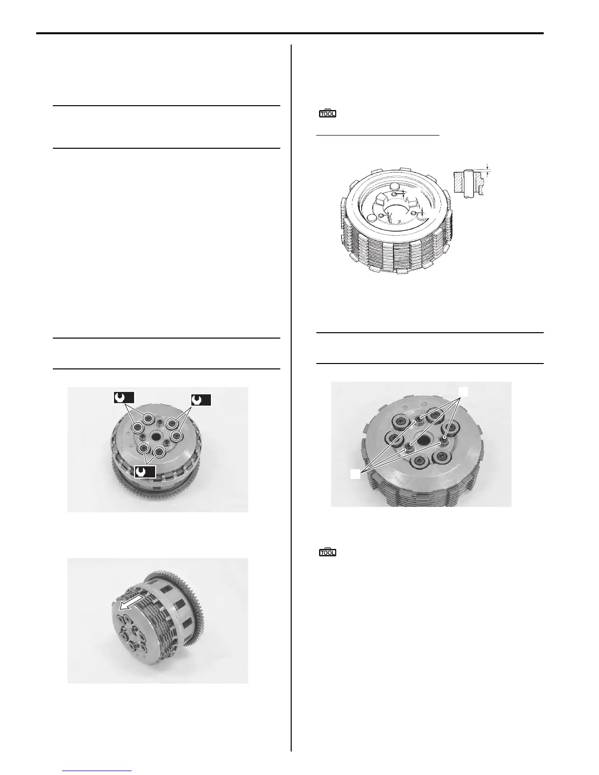
3) Inspect the height “A” of clutch lifter pin at three
positions using the thickness gauge. If the
measurement is out of the specification, adjust the
height “A” as shown in the figure.
Special tool
: 09900–20803 (Thickness gauge)
Clutch lifter pin height “A”
Standard: 0.2 – 0.4 mm (0.008 – 0.016 in)
4) Loosen the lock-nuts (1) and turn out the clutch lifter
pin (2).
NOTE
Each clutch lifter pin height should be as
closely as possible.
5) Set the thickness gauge to 0.3 mm (0.012 in).
Special tool
(A): 09900–20803 (Thickness gauge)
6) Place a proper flat plate on the thickness gauges
and hold them by hand.
7) Slowly turn in the clutch lifter pin (2) until resistance
is felt.
(a)
(a)
(a)
I947H1530038-01
I947H1530039-01
“A”
“A”
“A”
“A”
I837H1530044-01
1
2
I947H1530040-01
Manuals by Motomatrix / The Solution For Lost Motorcycle Coded Keys
email: info@motomatrix.co.uk / www.motomatrix.co.uk

 Loading...


