Emission Control Devices: 1B-7
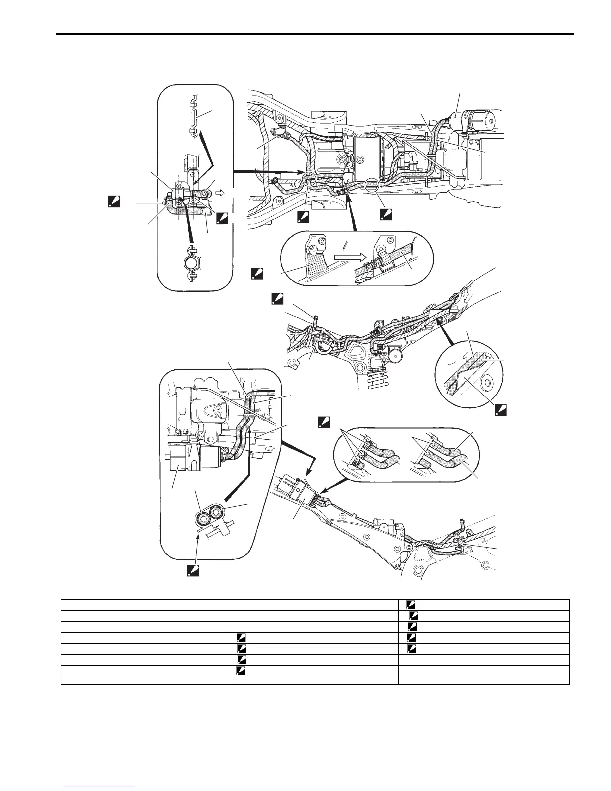
EVAP Canister Hose Routing Diagram (Only for E-33)
B947H11202002
1
1
2
2
2
2
2
2
3
3
3
3
3
3
5
1
6
6
6
7
“J”
“D”
“E”
4
“I”
“B”
“A”
“A”
“C”
“L”
“H”
“G”
“F”
“K”
I947H1120007-03
1. EVAP system purge control solenoid valve “A”: White marking “H”: Stick the clamp firmly in this area.
2. Surge hose “B”: Yellow marking “I”: Pass the hoses inside the parts holder.
3. Purge hose “C”: UP “J”: Face the clamp end forward.
4. Fuel shut-off valve “D”: Face the clamp end downward. “K”: Face the clamp end backward.
5. Rear fender “E”: Face the clamp end to the left. “L”: Face the clamp end to the outside.
6. EVAP canister “F”: Pass the hoses above the harness.
7. Seat hook “G”: Pass the hoses between the seat rail and
battery holder.
Manuals by Motomatrix / The Solution For Lost Motorcycle Coded Keys
email: info@motomatrix.co.uk / www.motomatrix.co.uk

 Loading...


