1A-54 Engine General Information and Diagnosis:
Step Action Yes No
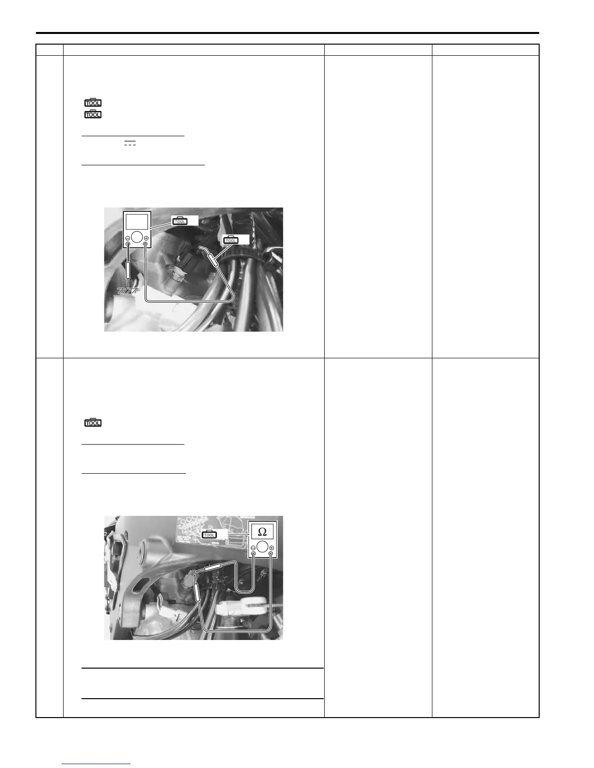
1 9) Measure the output voltage between the B/Bl wire and
ground.
Special tool
(A): 09900–25008 (Multi circuit tester set)
(B): 09900–25009 (Needle-point probe set)
Tester knob indication
Voltage ( )
ECT sensor output voltage
0.15 – 4.85 V
((+) terminal: B/Bl – (–) terminal: Ground)
Are the continuity and voltage OK?
Go to Step 2. • B/Bl wire shorted to
ground.
• If wire is OK, go to
Step 2.
2 1) Turn the ignition switch OFF.
2) Disconnect the ECT sensor coupler.
3) Measure the ECT sensor resistance.
Special tool
(A): 09900–25008 (Multi circuit tester set)
Tester knob indication
Resistance (Ω)
ECT sensor resistance
Approx. 2.45 kΩ at 20 °C (68 °F)
(Terminal – Terminal)
NOTE
Refer to “ECT Sensor Inspection” in Section 1C
(Page 1C-4) for details.
Is the resistance OK?
• B/Bl or B/Br wire
open or shorted to
ground, or poor “32”
or “35” connection.
• If wire and
connection are OK,
intermittent trouble or
faulty ECM.
• Recheck each
terminal and wire
harness for open
circuit and poor
connection.
• Replace the ECM
with a known good
one, and inspect it
again. Refer to “ECM
Removal and
Installation” in
Section 1C
(Page 1C-1).
Replace the ECT
sensor with a new one.
Refer to “ECT Sensor
Removal and
Installation” in Section
1C (Page 1C-4).
V
(B)
(A)
I947H1110024-01
(A)
I947H1110025-01
Manuals by Motomatrix / The Solution For Lost Motorcycle Coded Keys
email: info@motomatrix.co.uk / www.motomatrix.co.uk

 Loading...


