Engine General Information and Diagnosis: 1A-85
3 1) Turn the ignition switch OFF.
2) Connect the ECM couplers and STP sensor couplers.
3) Remove the air cleaner box cover. Refer to “Air Cleaner
Element Removal and Installation” in Section 1D
(Page 1D-6).
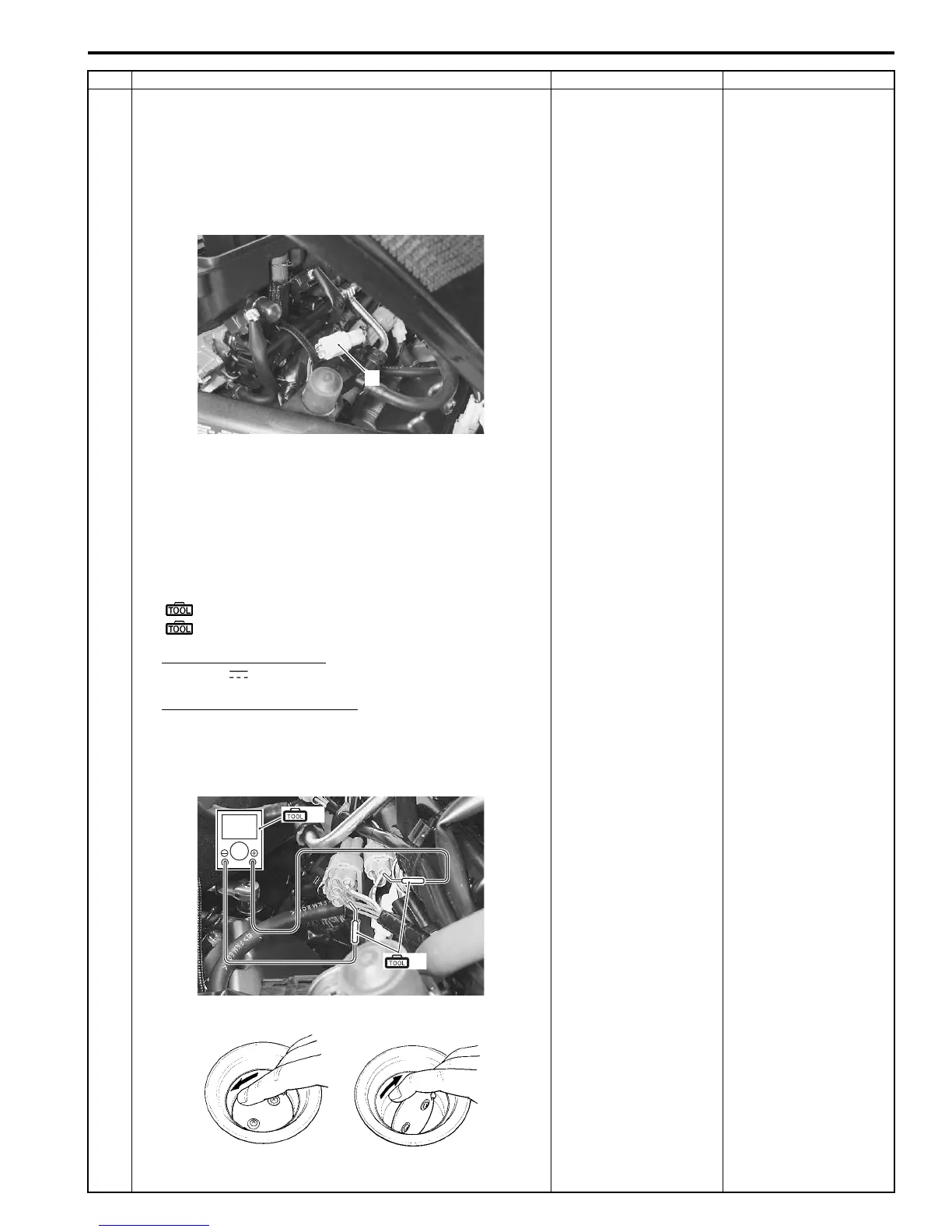
4) Disconnect the STVA lead wire coupler (1).
5) Insert the needle point probes to the lead wire coupler.
6) Turn the ignition switch ON.
7) Measure the STP sensor output voltage at the coupler
(between the Y/W wire (+) and B/Br wire (–)) by turning
the secondary throttle valve (close and open) with your
finger.
Special tool
(A): 09900–25008 (Multi circuit tester set)
(B): 09900–25009 (Needle-point probe set)
Tester knob indication
Voltage ( )
STP sensor output voltage
Secondary throttle valve is closed: Approx. 0.7 V
Secondary throttle valve is opened: Approx. 4.1 V
((+) terminal: Y/W – (–) terminal: B/Br)
Is the voltage OK?
• R, Y/W or B/Br wire
open or shorted to
ground, or poor “7”,
“18” or “35”
connection.
• If wire and
connection are OK,
intermittent trouble or
faulty ECM.
• Recheck each
terminal and wire
harness for open
circuit and poor
connection.
• Replace the ECM
with a known good
one, and inspect it
again. Refer to “ECM
Removal and
Installation” in
Section 1C
(Page 1C-1).
If check result is not
satisfactory, replace the
STP sensor with a new
one. Refer to “STP
Sensor Removal and
Installation” in Section
1C (Page 1C-7).
Step Action Yes No
1
I947H1110052-01
V
(A)
(B)
I947H1110053-01
I705H1110071-01
Manuals by Motomatrix / The Solution For Lost Motorcycle Coded Keys
email: info@motomatrix.co.uk / www.motomatrix.co.uk