COPYRIGHT
©
2001 CANON INC. 2000 2000 2000 2000 CANON iR8500/7200 REV.1 AUG. 2001
CHAPTER 2 NEW FUNCTIONS
2-49
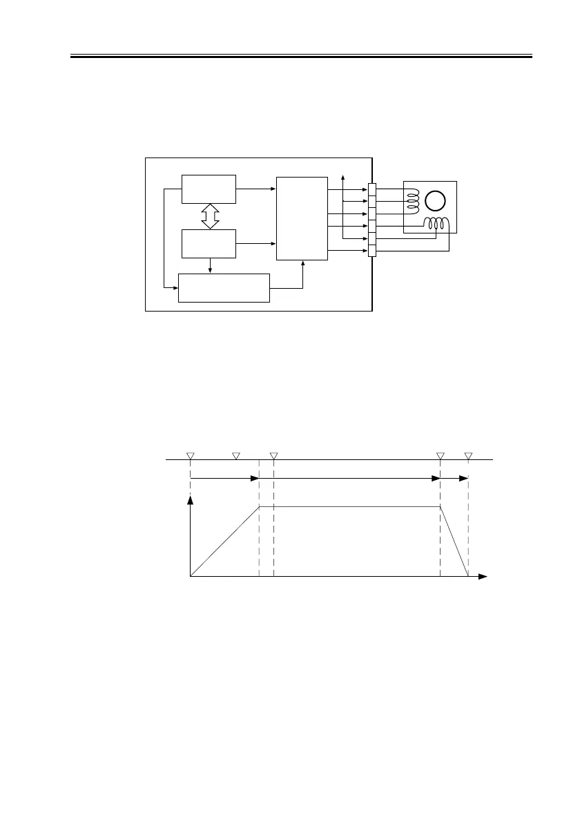
3.6.2 Controlling the Scanner Motor
The system used to control the scanner motor is constructed as follows:
The motor driver turns on/off the scanner motor and controls its direction and speed of
rotation in keeping with the signals from the CPU, IPC, and speed control circuit.
F02-306-02
a. Controlling the Motor When Scanning an Image
When scanning an image, the motor is controlled as follows, thereby controlling the
movement of the No. 1 mirror base unit:
[1] Acceleration: Used to accelerate until the speed most appropriate to the read ratio is
attained.
[2] Approach run: Used to ensure that speed stabilizes.
[3] Image read: Used to read the image at a specific speed suited to the read ratio.
[4] Deceleration: Used to enable the scanner to speed down and stop promptly, starting at
the end of the image.
F02-306-03
IPC
Scanner motor
Reader controller PCB
J5011
M3
1
5
2
3
6
4
A
A*
B
B*
+24V
Motor
driver
CPU
Speed control
circuit
HP Image leading edge Image end
Stream reading position
(start position)
Stop
Accelerate Maintain
Tra ve l
speed
Travel distance
[1] [2] [3] [4]
Decelerate

 Loading...


