COPYRIGHT
©
2001 CANON INC. 2000 2000 2000 2000 CANON iR8500/7200 REV.1 AUG. 2001
CHAPTER 6 TROUBLESHOOTING
6-116
Belt motor clock sensor (PI1)
3) Set the meter range to 10 VDC. Turn the belt motor by hand. Does
the voltage between J12-3 (+) and J12-2 (–) on the ADF controller
PCB change between 0V and 5 V?
NO: Replace the belt motor clock sensor (PI1).
Cable
4) Is the cable between the belt motor driver PCB and the ADF con-
troller PCB connected properly?
NO: Connect the cable correctly.
Belt motor driver PCB
ADF controller PCB
5) Replace the belt motor driver PCB. Is the problem corrected?
YES: Replace the belt motor driver PCB.
NO: Replace the ADF controller PCB.
4.1.48 E404 (Indicated if iR8500)
----------
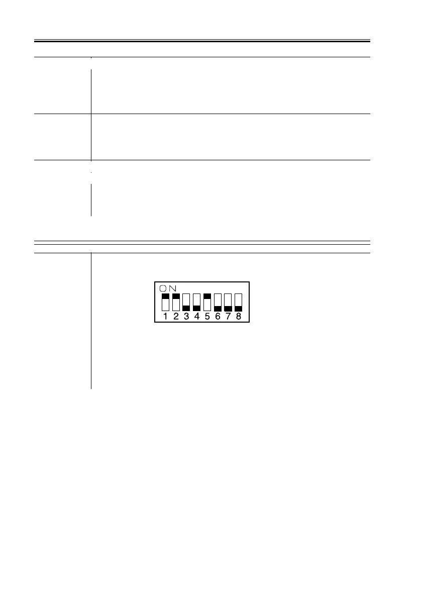
1) Set the DIP switch (SW1) on the ADF controller PCB as indicated.
F06-401-08
Press the push switch (SW2). Does the delivery motor (M5) rotate?
(To stop, press the push switch (SW2) once again.)
YES: Go to step 3.

 Loading...


