CHAPTER 3 MAIN CONTROLLER
3-8
COPYRIGHT
©
2001 CANON INC. 2000 2000 2000 2000 CANON iR8500/7200 REV.1 AUG. 2001
2 Digital image Processing
2.1 Outline
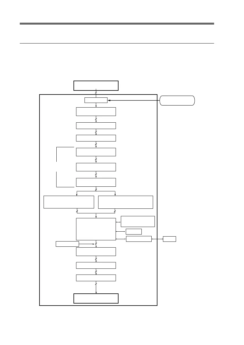
The image memory and the digital image processing mechanisms are controlled by the
main controller PCB; the following is a block diagram of the digital image processing
mechanisms:
F03-201-01 Block Diagram
8
Reader unit
Editing
Density correction
(LUT)
Binary processing
(error diffusion method; text,
text/photo, print photo)
Image memory
control
Binary processing
(dither screen method; film print)
8
Density correction
(γ conversion)
8
8
8
Edge emphasis
1
Compression/expansion,
rotation,
enlargement/reduction
SDRAM
I/O control
HDD
Image server
4 or 2
Thickening
4 or 2
1
Smoothing
1
Binary-binary density
conversion
Printer unit
Printer PG
1
8
8
Main controller PCB
Density adjustment
(F-value conversion)
Brightness/Density
conversion (LOG conversion)
Enlargement/Reduction
(main scanning direction)
Reader PG
Image data
after shading

 Loading...


