COPYRIGHT
©
2001 CANON INC. 2000 2000 2000 2000 CANON iR8500/7200 REV.1 AUG. 2001
CHAPTER 6 TROUBLESHOOTING
6-111
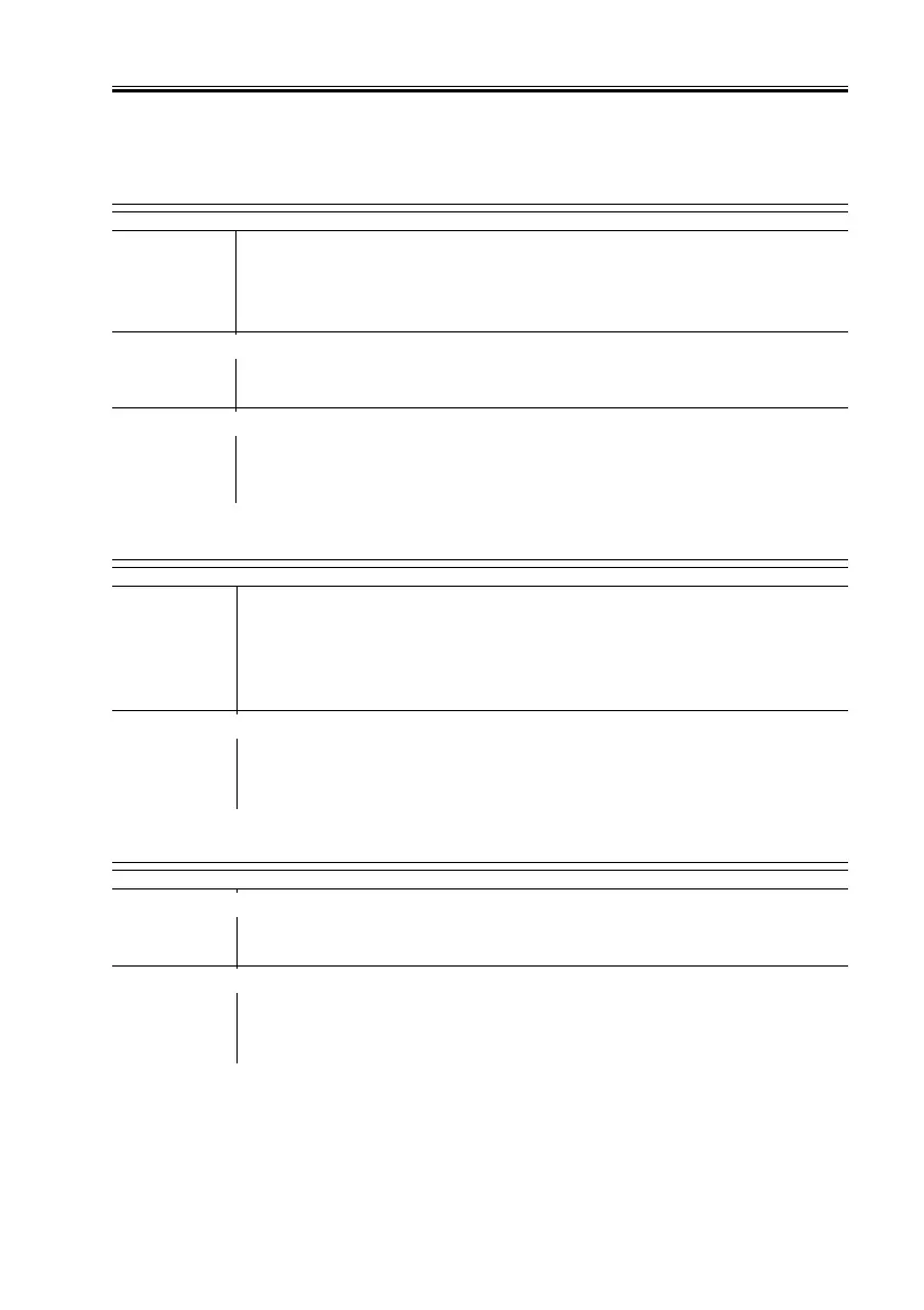
4.1.32 E219 (Indicated if iR8500)
4.1.33 E220 (iR8500)
4.1.34 E222 (Indicated if iR8500)
Connector
1) Are the connectors J852 and J853 on the light control PCB con-
nected securely?
NO: Connect the connectors securely.
Fluorescent heater
2) Try replacing the fluorescent heater. Is the problem corrected?
YES: End.
Light control PCB, Reader controller PCB
3) Try replacing the light control PCB. Is the problem corrected?
YES: End.
NO: Replace the Reader controller PCB.
4.1.35 E220 (iR7200)
Wiring
1) Is the wiring from the xenon lamp to the reader controller PCB
normal?
NO: Disconnect and then connect the connectors; correct or replace the
wiring.
Inverter PCB, Reader controller PCB
2) Try replacing the lamp inverter PCB. Is the problem corrected?
YES: End.
NO: Replace the reader controller PCB.
4.1.36 E225 (iR7200)
Xenon lamp (LA2)
1) Try replacing the xenon lamp. Is the problem corrected?
YES: End.
CCD unit, Reader controller PCB
2) Try replacing the CCD unit. Is the problem corrected?
YES: End.
NO: Check the wiring; if normal, replace the reader controller PCB.

 Loading...