CHAPTER 3 MAIN CONTROLLER
3-7
COPYRIGHT
©
2001 CANON INC. 2000 2000 2000 2000 CANON iR8500/7200 REV.1 AUG. 2001
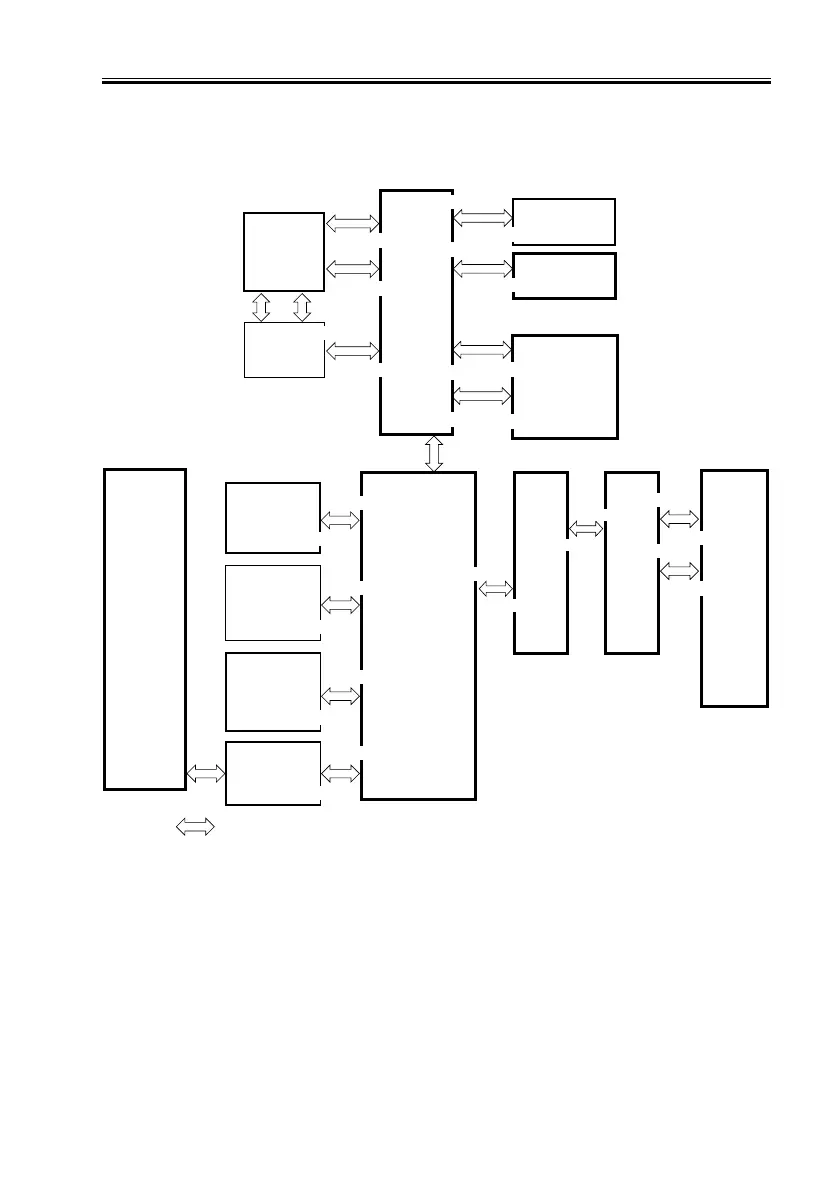
1.4 Inputs to and Outputs from the Major PCBs
1.4.1 Wiring Diagram of the Major PCBs
F03-104-01 Wiring Diagram of the Major PCBs
Controller
unit
Printer
unit
HDD
Reader
unit
Card Reader
D1
(option)
Copy Data
Controller
(option)
Pixel/Line
Conversion
PCB
J1024
J1022
J1015
J1451
J1017
J6801
J1018
J3
J2
J1014
J1551
J1532
J1530
LCD panel
(LCD)
Inverter
PCB
Control
Panel
CPU
PCB
J6808
J6807
J6804
J6803
J6802
Note: The in the diagram indicates major connections, NOT the flow of the signals.
J6605
J6901
J6601
J6805
J6602
J1
Key B PCB
Key A PCB
J6806
Key C PCB
J9201
J1104
J9202
Printer
Differ-
ential
PCB
Reader
Differ-
ential
PCB
J5008
J5503
J5004
J5501

 Loading...


